

Nonlinearity with spike-like behavior
In electronics it is possible to create high current spikes when one uses the exponential relation between current and applied voltage across a diode in forward direction.
A model for an ideal diode is
![]()
Here V is the applied voltage in forward direction, q is the unit of charge (charge of 1 electron), k is Boltzmann's constant and T is the temperature in Kelvin. At room temperature q/kT is approximately 1/0.026 V.
The current I0 is the so-called saturation current, which typically is in the order of 1 nA. The current I is the current flowing through the diode. This model has the property that for voltages up to a few tenths of volts the current through the diode is negligible and then suddenly for increasing voltage it grows very rapidly.
A real physical diode suffers from physical effects, which result in deviation from the above equation. Two main effects exist, one being that the exponent usually has a smaller value than qV/kT (up to an almost constant factor of 2 smaller) and there also may be a series resistance of a few ohms in series with the idealized diode. So, a better model, but still without the series resistor is
![]()
Here, the parameter n is used to take into account the lower value of the exponent in real diodes. For one of the best-known types of diodes, the 1N4148 small signal diode, the value of n is somewhere around 1.3. When temperature is considered more or less constant (somewhere between 15 and 25 ºC), then the diode model can be written as
![]()
where A can be written as 38.4/n. For the 1N4148 diode the constant A is somewhere around 30.
For real diodes, such as the 1N4148 the saturation current I0 is in the order of magnitude of nano amperes or hundreds of pico amperes. A good starting value is to take this parameter equal to 1 nA.
The series resistance of a 1N4148 is somewhat uncertain. Many different values are listed, some of them as low as 0.6 Ω, but also values as high as 13 Ω have been reported and the real value probably can be safely assumed to be in the order of a few Ω's. Just to be sure that the series resistance hardly matters anymore, an external resistor of 100 Ω is placed in series with the diode in the real circuit. The total series resistance now hardly is affected by the series resistance of the diode. The circuit, used for generating a highly non-linear voltage to current conversion is the following:
The diode is a 1N4148 and the resistor is a 100 Ω standard carbon film resistor with a tolerance of 5%.
The current through this series cannot simply be written as a mathematical function of the applied voltage over the series connection of the two components, no analytical expression can be given for that, but when a graph is drawn of the current as function of voltage across both components, then it roughly looks as follows:
For small voltages, the diodes' exponential function dominates, but from approximately 0.65 volts, the linearity of the 100 Ω resistor dominates. Computing the current as function of applied voltage can be done numerically by means of an iterative procedure.
A first order system is obtained by integrating the current I into a capacitor. This is done by means of an opamp. The total circuit for generating the delayed spike for large values of x is as follows:
When the input voltage Vin is taken equal to x and the output voltage Vout is taken equal to z, then one can write:
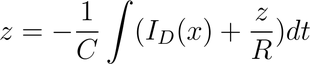
When it is rewritten in the form of a differential equation this is
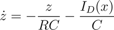
Here, ID(x) is the current through the diode and the 100 Ω resistor as function of voltage x across the two endpoints of this circuit. For large x, this produces a strong spike, which is integrated into z. When the value of x falls back to a low value, then ID(x) essentially becomes 0 and then the other term –z/RC assures that z itself asymptotically goes towards 0 also.
Note that the above circuit produces a negative spike for positive x, so we need to invert the signal z, which of course is very simple, using another opamp and two equal resistors. The total circuit for z then is
back to chaotic oscillator page