
Relaxation oscillators
In physics many processes can be described as oscillator. There exist many different types of oscillators. Usually oscillators are associated with electronics, but they also exist in the mechanical domain, and even in the chemical domains and biological domains. Different types of oscillators can be distinguished:
- Harmonic oscillators. These appear, where a physical object feels both inertia (based on speed) and force (based on velocity). Objects move around a certain equilibrium point. One can think of a mass-spring system, which oscillates around its equilibrium point. One can also think of an LC-circuit, where energy is stored alternatingly in a capacitor (potential energy, comparable to potential energy in a deformed spring) and in an inductor (kinetic energy, comparable to kinetic energy of a moving mass). Masses, orbiting around each other in some sense also can be regarded as forming an harmonic oscillator system. In order to make a stable harmonic oscillator, some amplitude control mechanism is required. If such a control is not used, then the oscillator either will die out, or its amplitude will go out of control.
- Time delay oscillators. Consider a system with an input and an output. For stationary input, the system has a gain, with an absolute value, larger than 1. For dynamic input, the output is an amplified version of the input signal, but with a certain time delay. When the output is connected to the input, then the system will oscillate. This type of oscillators appear in electronics (e.g. when an odd number of NOT-gates is connected in series, and when the output of the last gate is connected to the input of the first one). This type of oscillators also appears in Nature, e.g. in prey/predator systems, where a decreasing number of predators results in an increasing number of preys, with a certain time delay. The feedback then consists of the available preys for the predators. The number of preys and predators can show wildly oscillating behavior over time.
- Phase shift oscillators. Consider a system with an input and an output, and a inverting gain, larger than 1. The gain, however, is frequency dependent, and there is a phase-shift between the input signal and the output signal. At a certain frequency, the output is shifted 180 degrees, relative to the input. At that frequency, the gain seems to be positive. When the output of such is system is connected to the input, then the system will oscillate at the frequency, where the phase shift is 180 degrees. This kind of oscillators vaguely resembles the time delay oscillators. Time delay can in some sense be regarded as phase shift as well.
- Relaxation oscillators. These are the subject of this page and will be described in more detail. One also can visualize this type of oscillator nicely by means of very simple electronic circuits.
![]()
Basics of relaxation oscillators
A relaxation oscillator exists in almost all physical domains. In order to obtain a relaxation oscillator, one needs a source of a certain quantity (quantity can be volume of water for hydraulic systems, electric charge for electrical systems, displacement for mechanical systems). One needs a buffer, which can store some of the quantity, but with the special property, that when the amount of quantity in the buffer exceeds a certain level, the storage system will break down and the quantity, stored in the buffer, is purged from the buffer at once, or at least in a very short time.
The picture below shows how a relaxation oscillator works. From an unlimited source of quantity, quantity is taken with a certain speed. Usually the speed is limited by some resistance (e.g. an electrical resistor, or a tube, which limits liquid flow). Quantity flows from the source to the buffer. At a certain point, when the amount of quantity in the buffer exceeds its breakdown quantity, then suddenly the contents of the buffer is dumped. The flow of quantity from source to buffer continues, and hence this results in a repeating pattern of slowly filling the buffer, dumping (most of) its contents and then slowly filling it again, ad infinitum.
On this page, some simple relaxation oscillators are shown, which can be built easily and for which the breakdown of quantity can be easily visualized. In electronics, this type of oscillator is well-known and it also is used in many circuits, but on this page, these circuits are not presented, because that would require knowledge of specific electronic components and usually, the oscillation also cannot be easily visualized without special equipment.
Here, two types of relaxation oscillators are covered, which very nicely demonstrate the effect of buffer breakdown. The one is a dripping faucet, and the other is a capacitor, charged to a certain voltage and when the voltage exceeds a certain level, the charge on the capacitor is dumped quickly, giving a nice physical effect.
![]()
Required equipment for neon experiment:
- power supply, capable of providing a DC voltage between 150 and 400 V. Any voltage in this range will do. See here for more info on the needed power supply.
- capacitor, rated for 400 V, with a capacity of 100 nF to 1 μF. Any value between these extremes is perfectly suitable.
- resistor (or set of resistors making up a value) of 5 to 10 MΩ.
- a small neon bulb, type NE-2.
- some wires and crocodile clamps, and some soldering tin for making the circuit. A breadboard also can be used.
Required equipment for xenon experiment and spark gap:
- power supply, capable of providing a DC voltage of at least 10 kV. See here for more info on a suitable power supply. One can also use the high voltage circuit of a TV or monitor, these can provide voltages well over 10 kV.
- capacitor, rated for 15 kV, with a capacity of 1000 pF to 5000 pF. Any value between these extremes is perfectly suitable.
- high voltage resistors (20 to 50 MΩ for the spark gap, 500 to 1000 MΩ for the xenon tube).
- a xenon flash tube. Any type is suitable. One can also take a flash tube from an old camera or flash unit. It does not need to be a ∩-shaped tube.
- some wires and crocodile clamps. Either solder the circuits, or use clamps, free floating in air. Do not use breadboard for these very high voltage circuits.
Safety:
- All of the high voltage experiments are dangerous. The voltages, involved in the experiments can be lethal, especially the really high voltages, used in the xenon-tube and spark gap experiments.
-
 The experiments
require the use of capacitors. Especially the capacitor, charged to several
kV can give a really nasty shock. Be sure to have this discharged before
touching anything and before disassembling the circuits. A shock from a
capacitor of several nF, charged to 10000 V can be lethal, but a shock from
a capacitor of several 100's of nF, charged to 300 V also is not fun at all.
Also keep in mind, that capacitors keep their charge for hours, or even days
or weeks.
The experiments
require the use of capacitors. Especially the capacitor, charged to several
kV can give a really nasty shock. Be sure to have this discharged before
touching anything and before disassembling the circuits. A shock from a
capacitor of several nF, charged to 10000 V can be lethal, but a shock from
a capacitor of several 100's of nF, charged to 300 V also is not fun at all.
Also keep in mind, that capacitors keep their charge for hours, or even days
or weeks. -
NO YOUNG KIDS
AROUND, NO PETS AROUND, while the high voltage circuits are operational.
They will touch the very interesting stuff!
The dripping faucet experiment, explained below, can be done with any faucet in the house, which can be adjusted precisely. The other oscillator circuits require some equipment. One can also decide to perform only part of the experiments.
![]()
Dripping faucet
A very common phenomenon, known by everybody, is a
dripping faucet. If water is allowed to flow at a very low rate, then drops of
water are formed every few seconds (or even
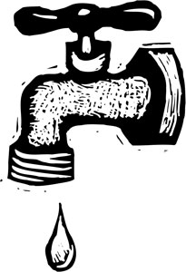 minutes).
This can be regarded as a relaxation oscillator. The buffer is the area
at the bottom of the faucet (the nozzle), where water can be kept, due to the
surface tension of the water and the attraction of the water to the metal of the
faucet. When water is flowing very slowly, then the amount of water at the
nozzle slowly grows. The gravitational pull on the water becomes larger and
larger and then at a certain point, surface tension and adhering forces break
up, and the drop of water is released. Suddenly the buffer is emptied, and the
amount of water at the nozzle is almost zero again. Only a small amount remains
there, which snaps back when the drop is released. Slowly a new amount of water
builds up, until again, the gravitational pull breaks down the surface tension
and adhering forces. The quantity is the volume of water, sticking to the
nozzle. The resistance is formed by the tap, which is almost completely
closed. The source of quantity is the municipal water system, which
supplies water to all households.
minutes).
This can be regarded as a relaxation oscillator. The buffer is the area
at the bottom of the faucet (the nozzle), where water can be kept, due to the
surface tension of the water and the attraction of the water to the metal of the
faucet. When water is flowing very slowly, then the amount of water at the
nozzle slowly grows. The gravitational pull on the water becomes larger and
larger and then at a certain point, surface tension and adhering forces break
up, and the drop of water is released. Suddenly the buffer is emptied, and the
amount of water at the nozzle is almost zero again. Only a small amount remains
there, which snaps back when the drop is released. Slowly a new amount of water
builds up, until again, the gravitational pull breaks down the surface tension
and adhering forces. The quantity is the volume of water, sticking to the
nozzle. The resistance is formed by the tap, which is almost completely
closed. The source of quantity is the municipal water system, which
supplies water to all households.
The dripping faucet is a particularly interesting relaxation oscillator, because it can exhibit chaotic behavior. When the flow of water is increased slowly, then the drops of water build up faster and the interval of time between two drops of water becomes shorter. At low rates, the interval of time between two drops is constant and the dripping is very regular:
.....drip..........drip..........drip..........drip..........drip..........drip..........drip.....
When the flow of water is increased, then the drops of water simply follow each other at a higher rate:
....drip........drip........drip........drip........drip........drip........drip....
But, when the flow of water is increased beyond a certain point, then the time between two drops is not constant anymore. It alternates between a shorter and a longer interval, so now there are two intervals.
....drip......drip.........drip......drip.........drip......drip.........drip...
At even higher flow, there can even be four different intervals between drops of water:
..drip........drip...drip.....drip....drip........drip...drip.....drip....
This can go on, with ever higher irregularities, until finally the behavior is totally chaotic and the interval between drops is very irregular.
This process of doubling the number of intervals of different length and the final chaotic behavior with increasing flow is called bifurcation. This is not specific to relaxation oscillators, but it is quite common in processes, which behave like relaxation oscillators.
This effect can easily be observed at home with any faucet. Adjust the faucet, such that it drips very slowly and carefully allow it to drip faster. At a certain point, the bifurcation can easily be observed, even without stopwatch. The time between drops is varying between a longer and shorter interval. Observation of the second bifurcation to four different intervals still is possible without measuring equipment, but it requires very careful observation. Higher bifurcations cannot be observed with the bare eye and one's sense of time. Then measuring equipment is needed, such as IR-laser detection systems.
In the case of the dripping faucet, this chaotic behavior is due to interaction between drops. After pinching off, the largest part of the drop falls, and there is a snapback of the water droplet still adhering to the nozzle. When the drops are arriving at a sufficiently high rate, the snapback does not fully complete before the next drop is about to pinch off. As the drop falls, the water column that suspended it rebounds and vibrates and this affects the timing of the falling drops in a very complicated and non-linear matter. Each falling drop modifies the timing of the next drop due in part to oscillations of the water column. Also, the timing of the falling drop affects the time needed to reform the next drop before it falls.
![]()
Neon bulb relaxation oscillator
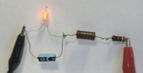
A very nice and easy to build relaxation is based on a neon bulb, and a capacitor. The capacitor is slowly charged through a resistor. This causes the voltage across the capacitor to rise slowly. The neon bulb is connected to the terminals of the capacitor. A neon bulb is a perfect isolator, as long as the voltage over it remains below approximately 70 V. When the voltage exceeds a certain threshold, then the gas in the bulb becomes ionized and a conductive path is produced. This is the breakdown of the gas in the neon bulb. As long as sufficient current is flowing through this path, the path remains intact, even if the voltage across the bulb drops well below 70 V. The capacitor supplies the current to keep the path of conduction intact, until it is almost completely discharged. At that point, conduction stops and the neon bulb becomes an isolator again. The capacitor then slowly is charged again, until the next breakdown occurs in the neon bulb.
The cycle, described above, continues over and over again and makes a perfect oscillator, which is quite stable. Visualization of this oscillation is very easy, because as long as the bulb conducts current, it emits a bright orange light. Below follows a picture of a complete circuit, which is connected to a DC voltage source, somewhere between 150 and 400 V DC.
The circuit diagram is given below. The two resistors in the real circuit were taken from on old TV and and they were selected to give approximately 5 MΩ total resistance. The values, given here, are not critical at all. Increasing the resistance results in lower oscillation frequency. The value should not be decreased too much, because that may result in continuous emission of light from the neon bulb. When the charge of the capacitor is dumped, then the current, supplied through the resistor should not be sufficient to keep the gas in the bulb ionized at the voltage, which remains, immediately after discharging of the capacitor.
The voltage of the power supply may be anywhere between 150 V and 400 V. Increasing the voltage results in higher oscillation frequency (the charge current is higher).
In this example of the relaxation oscillator, the quantity is the electrical charge, stored in the capacitor. The buffer is the capacitor itself, and the breakdown is due to the neon bulb becoming conductive at once, when the voltage across it exceeds approximately 70 V.
The oscillation frequency of such a neon bulb relaxation oscillator is quite stable. Each time, a discharge through the neon bulb is approximately the same. It starts at a certain breakdown voltage and each time, the capacitor is discharged in approximately the same (short) time and reaches the same final voltage. The voltage as function of time can be drawn as follows:
The oscillation frequency is a function of the product of the resistance and capacitance, and the breakdown voltage and the voltage, at which the bulb becomes non-conductive again. For the selected components, the frequency is approximately 2 Hz for a voltage of 300 V. The top of each saw-tooth is at 70 to 80 volts, the bottom of each saw-tooth is at 20 to 30 V, but the actual values strongly depend on the actual neon bulb used.
![]()
Xenon flash tube relaxation oscillator
A somewhat more spectacular relaxation oscillator can be built with a xenon flash tube. The idea behind this relaxation oscillator is exactly the same as the idea behind the neon bulb relaxation oscillator, but the voltages, used here, are much higher. A xenon flash tube does not fire below approximately 3 kV, it requires a much higher breakdown voltage.
The circuit diagram for the xenon flash tube oscillator is shown below:
A high voltage capacitor is used for the 2.2 nF capacitor, and the resistor was built by connecting 45 resistors of 22 MΩ in series. When this circuit is built, then the circuit indeed oscillates, but the oscillation is very irregular. There is not a specific frequency, but the behavior seems to be chaotic. The time between two flashes is varying wildly. The following picture shows the irregular oscillation of this circuit:
The picture shows the xenon tube, the trigger is not connected (the strip, connecting the two legs of the tube), the poles of the tube are connected to a 2200 pF/15 kV capacitor.
The irregularity can be explained by the irregular shape of the discharge sparks inside the flash tube. If a fat spark is produced, then the capacitor is almost completely discharged, if a thin spark is produced, then the capacitor is still charged quite a lot and recharging the capacitor before the next discharge occurs takes less time. The voltage across the xenon tube looks like a saw-tooth signal, but irregular. The discharge also is much faster as with the neon bulb. A discharge is a single spark, which only takes a tiny fraction of a second.
![]()
Spark gap relaxation oscillator
The most spectacular relaxation oscillator can be made by means of a simple capacitor circuit and a resistor, with a spark gap, placed across the terminals of the capacitor. This requires a very high voltage of several kV. Good results require at least 10 kV, but preferably more.
This experiment again was conducted with a 15 kV power supply. The resistor was replaced by a 40 MΩ resistor, the capacitor was kept the same. The xenon flash light was replaced by two needles, with a spark gap between the tips of the needles. The capacitor charges through the resistor and when the voltage exceeds a certain level, then a fat and noisy spark is produced. The amount of energy per discharge is much higher than in the previous experiment. The voltage across the capacitor will be between 10 kV and 15 kV just before discharge, while with the xenon bulb, the voltage is around 3 kV just before discharge. The amount of energy, released in a single discharge will be at least 10 times as high.
The diagram of the circuit, used for the spark gap oscillator is given below:
This system shows oscillations at a frequency of a few Hz of moderate stability. The rate of oscillation is more stable than with the xenon flash tube, but it is less stable than with the neon bulb. The oscillation is accompanied with a lot of noise. Each spark gives a loud crack. The image below shows the oscillation of this circuit: