

Power supply 115/230 V AC, 160/320 V DC
Many experiments on this site use relatively high voltages, 115 V AC or 230 V AC, and also DC voltages somewhere from 100 to 300 volts. If you just want to do one or two experiments, then you could use the voltage from the wall outlet, but there is a severe risk of shock when doing so. A much safer approach is to use a 1 : 1 transformer, or a center-tapped 1 : ˝,˝ transformer.
This page shows some very easy to build and simple circuits, which are perfectly suitable for all experiments with medium high voltages on this site, such as experiments with neon bulbs and experiments with ordinary tungsten bulbs. One circuit emphasizes on cost, the second emphasizes on safety.
Simple circuit, ultra low cost
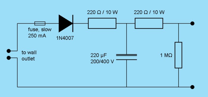
If you don't want to invest too much on a power supply for experiments, then the following circuit is very useful for most DC voltage experiments on this site. In countries with 110 to 120 V AC, a voltage of approximately 160 V is produced at the output. For those countries, a capacitor, rated for 200 V can be used for filtering. In countries with 220 to 240 V AC, a voltage of approximately 320 V is produced at the output. For those countries, a capacitor, rated for 400 V should be used. When building this simple power supply, assure that the electrolytic capacitor is connected at right polarity, otherwise it may vent gasses, or may even explode.
![]() When this circuit is used, then keep in mind that not a single component may be
touched, while the circuit is 'life'. Touching any component may result in
severe shock, because you are working directly from the mains.
When this circuit is used, then keep in mind that not a single component may be
touched, while the circuit is 'life'. Touching any component may result in
severe shock, because you are working directly from the mains.
Although this circuit is not regulated and only has a capacitor, for reducing ripple voltage, it is OK for all the experiments on this website, which require voltages in the order of magnitude of a few hundreds of volts. All these experiments only require currents in the order of magnitude of several tens of μA, so there is no real need for voltage regulation beyond the simple ripple suppression by means of the electrolytic capacitor.
This circuit is fairly safe with respect to shortcircuiting. If that occurs, then the fuse will be blown, but not any other component. There is quite some output resistance for this circuit, but that is of no concern in the experiments, described here. At a current of a few tens of μA, the total voltage across the two resistors will only be in the order of millivolts. Even when 1 mA is drawn, the total voltage drop across these resistors only is 0.44 V.
Finally, it is very important to add the resistor of 1 MΩ as an internal load. This is used as so-called 'bleeder resistor'. It slowly discharges the capacitor, when the circuit is unplugged. Do not omit this resistor. It may safe your life! When this resistor is not added, then the charge on the capacitor may remain there for a very long time and when you later pick up the circuit, then you may have a very nasty shock from the charge, still present on the capacitor, even if it was unplugged for hours or even days. A discharge of a 220 μF capacitor, especially, when it is charged to well over 300 V may be lethal, so be careful, even if the circuit is unplugged.
Simple circuit, with much better safety properties
When one is intending to perform a little more experiments in the hundreds of volts range, then it is strongly advised to spend a little more money on safety. How much do you value your life? The more experiments you do, the higher the risk of fatal shock. After some time people tend to be too comfortable with dangerous things and for such cases, it really is worth the investment of a few tens of dollars. For that additional money you also can buy yourself a little more flexibility.
If you are in a country with a voltage near 230 V AC, then either purchase two small step down transformers, or even better, purchase a single transformer, with 2 times 115 V AC output. This type of transformer is quite common and is available at most electronics parts stores. Only a small transformer is needed, e.g. 50 Watt total output is more than ever is needed. Whatever solution, with either two, or one transformer, you have 2 x 115 V AC, isolated from the mains.
If you are in a country with a voltage near 115 V AC, then purchase two 1 : 1 transformers, which usually are used as isolation transformers. With these two transformers you also have 2 x 115 V AC, electrically isolated from the mains.
These two transformers must be connected in such a way, that one center-tap is created and two 115 V AC outputs, which are anti-phase, relative to each other. Between these points, then there is 230 V AC.
Below follows the circuit diagram of the somewhat more involved power supply. At the left, the two transformers (or one transformer with two independent 115 V AC secondary windings) are shown, which must be connected to the wall outlet.
At the secondary side, there is a very nice symmetric setup, which allows one to create 115 V AC, or 230 V AC and at the same time, relative to the same GND (zero volt) terminal a fully rectified and filtered 160 V DC and -160 V DC. One can also create a single voltage of 320 V DC. This simple power supply is much more versatile than the one, shown above, and it also is much safer. One can safely touch one lead in the circuit, in which one is experimenting. Of course, one still has to be very careful not to touch two points in the circuit, because that again would create a closed loop through the body. So, this circuit certainly is not idiot-proof and only persons, who know what they are doing should be allowed to work with it. It is very important not to ground the GND terminal to earth. Doing so would remove the safety benefit of the use of transformers. That would make working with this power supply as dangerous as working directly from the mains.
The capacitors in the circuit must be electrolytic capacitors, rated at 200 V DC. Also, for this circuit, do not omit the bleeder resistors of 1 MΩ. Again, these could safe your life! A shortcircuit of this power supply will result in a loud bang and a big spark, and blowing of the fuse, but no other components will be destroyed. The 6A100 diodes are very robust and are not easily blown out. This power supply is more powerful than the simple one, shown above. No series resistors are needed anymore, the initial surge is limited somewhat by the transformer, and the diodes, used in this supply are much more robust. So, no resistor is needed for limiting the charge current of the electrolytic capacitors.
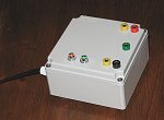
The physical buildup of this power supply can be really simple. I have built this power supply into a little plastic box (11 x 11 cm), with 5 terminals on top of it:
- green: GND, all other voltages are relative to this.
- yellow: 115 V AC (two terminals, anti-phase, 230 V AC between these)
- red: +160 V DC
- black: –160 V DC
There are two small neon indicator lamps, showing that it is connected to the mains (orange one) and showing charge present in the capacitors (green one, in series with 1 MΩ bleeder resistor, placed over the full 320 V DC output). When the power cord is unplugged, the green indicator light will be lit for several minutes, providing a visual indication of a dangerous charge on the capacitors and hence a still dangerous voltage on the red and black terminals.
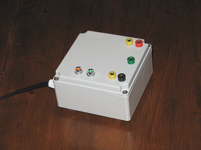
Using a power supply like this, one can relatively safely perform experiments with voltages up to a few 100's of volts, provided, some good insulated test leads are made, which nicely fit into the plugs on the box.
Total cost of this simple, yet versatile power supply was approximately $40, of which the transformer and the box were the most expensive parts.
back to miscellaneous main page