

Magnet launching
This little experiment shows a fundamental connection between electricity and magnetism in a very instructive way. Some special items are needed, but all of these can be purchased at any electronics parts shop, through eBay, or at a hardware store. This experiment is very safe and even can be conducted by fairly young children, but still, it is strongly advised to have adult supervision while the kids are experimenting.
In this experiment, a capacitor is charged from a power supply. The capacitor then is discharged through a very primitive coil. This induces a magnetic field for a short time. This magnetic field is strong enough to launch a small neodymium magnet. The effect is quite surprising for younger children, who really like this experiment.
Depending on used voltage and used capacitance, the magnet can be launched a few centimeters, to almost one meter, while still being perfectly safe!
![]()
Required equipment:
- simple power supply, giving a voltage between 10 and 20 volts. A fixed power supply is perfectly suitable. One can also use two 9 V batteries, connected in series.
- electrolytic capacitor, rated for 20 volts or higher and having at least a capacity of 10000 μF to 30000 μF. A few smaller capacitors, connected in parallel also work well.
- some wires with crocodile clamps at each end.
- a small tube, preferably transparent.
- a small cylindrical neodymium magnet, which fits in the tube, but cannot rotate freely inside the tube.
- a 100 Ω resistor, rated for 1 W power consumption.
Safety:
- The electrolytic capacitor must be charged with the right polarity. Using reverse polarity results in damage of the electrolytic capacitor. It may start leaking and venting gas. When it is connected to reverse voltage for prolonged time, it may even explode!
![]()
Setup of the experiment
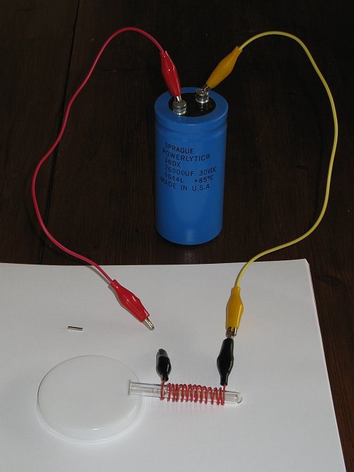
The setup for this experiment is very simple. One needs a DC power supply, for charging a capacitor, and one needs to make a simple coil, by winding a wire around a thin tube.
Charging of capacitor
In order to make the charging safer and less sparky, it is recommended to use a 100 Ω resistor in series with the power supply.
The circuit for the charging is as follows:
The capacitor simply is connected to the resistor and the negative pole of the power supply for 10 seconds or so and then it is taken away. After this, the capacitor is fully charged at the voltage of the power supply.
The capacitor, used in the experiment presented here, is a 26000 μF capacitor. This capacitor is charged to 13.8 V, the voltage of a common car battery charger. Any voltage between 10 V and 20 V will do. A picture of the capacitor follows below.
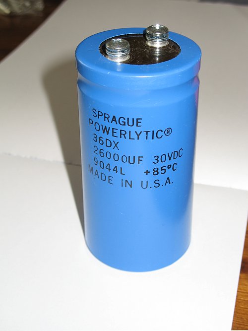
The capacitor can be charged safely to voltages of 30 V, but in the experiment, described here, it only is charged to around 10 V and 13.8 V.
Preparation of the coil and selection of magnet
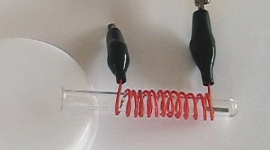
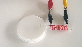
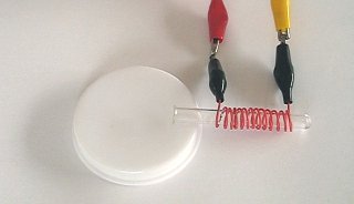
Making the coil is very simple. Take a small tube, with an inner diameter of a few mm and wind some wire around this tube. It is not necessary to make tight windings or to make many windings. A very crude coil is sufficient for this experiment. The lower the capacitance of the capacitor used, the more windings are required for the coil in order to obtain the desired effect at sufficient strength. Below follows a picture of the crude coil, made for this experiment. This coil worked very well for a 26000 μF capacitor at 13.8 V, with a neodymium magnet, which has a length of 10 mm and a diameter of 2 mm (a long thin rod). The picture below shows the magnet and the crude coil.
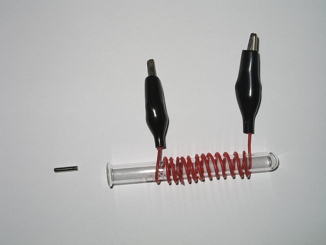
The little tube has an inner diameter of 6 mm and an outer diameter of 8 mm. Only 13 windings are made around this small tube and these windings are not tight at all. When a lower capacitance of e.g. 10000 μF is used, then one could use 30 windings of thinner wire, more tightly wound around the tube and still obtain good results. Any tube is suitable, as long as it is smooth inside and not made of magnetic material. It is nice if it is transparent, but that is not required for the experiment. The tube also may be open at both ends.
As the picture shows, the magnet is a thin cylindrical rod, with 10 mm length and 2 mm diameter. It is magnetized along the long direction of the rod, with the north and south poles at the ends of the rod. The magnet must be a strong neodymium magnet, N40 or better.
Circuit for launching the magnet
Launching the magnet is very easy. Put the magnet in the tube and connect the capacitor to the two connectors of the crude coil. The orientation of the magnet determines the direction into which it is launched. In the experimental setup, shown here, the tube is closed at one side, so one must determine the right orientation of the magnet, when it is put in the tube. This can simply be done by trial and error. If the magnet is oriented in the wrong way, then it will be launched towards the bottom of the tube and there hardly is any visible effect.
The total launching circuit looks as follows:
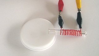
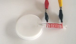
The fully charged capacitor is connected to one side of the crude coil, the other side still is left open. The open end of the little tube is placed on a thin disk (appr. 7 mm height) in order to obtain a little tilt. When the magnet has to be launched, then the red crocodile clamp is moved towards the left black crocodile clamp and when they touch, the magnet is launched. After each shot, the two terminals of the charge circuit (see above) are connected to the terminals of the capacitor for 10 seconds in order to recharge it.
 The
magnet must be put inside the tube, such that it is halfway covered by
the crude coil and on launching will move through the coil. Initially, the
magnet must only be partially covered by the coil (between 25% and 50%). The
picture at the left shows how the magnet must be positioned, relative to the
coil. With a tube, which is closed at one end, this is achieved easiest, by
placing the coil approximately 75% of the length of the magnet from the bottom
of the tube. Using this initial position gives the
best results.
The
magnet must be put inside the tube, such that it is halfway covered by
the crude coil and on launching will move through the coil. Initially, the
magnet must only be partially covered by the coil (between 25% and 50%). The
picture at the left shows how the magnet must be positioned, relative to the
coil. With a tube, which is closed at one end, this is achieved easiest, by
placing the coil approximately 75% of the length of the magnet from the bottom
of the tube. Using this initial position gives the
best results.
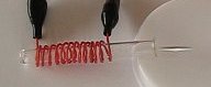
Launching the magnet
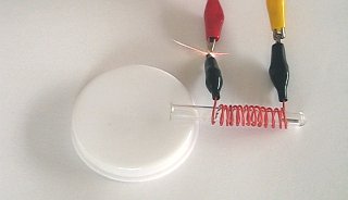
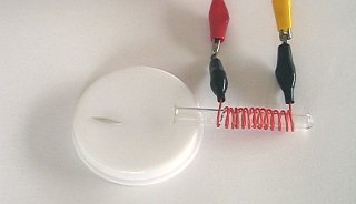
The fully charged capacitor is short-circuited over the coil, by touching the open terminal of the coil (one of the black crocodile clamps) with the open terminal of the capacitor (the red crocodile clamp from the picture above). The result will be a small spark when the two terminals touch each other and immediately after that, the magnet will be launched. With the capacitor of 26000 μF, charged to 13.8 V, the magnet is launched approximately 20 cm from the open end of the tube. With the capacitor charged to 10 V, the magnet is launched approximately 4 cm from the open end of the tube.
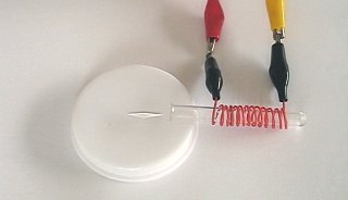
Below, a sequence of 12 pictures is shown, 33 ms between each frame. The first frame shows the situation, just before the capacitor/coil circuit is closed. The second frame shows the moment of closing the circuit and the subsequent frames show how the magnet is launched.


The launching of the magnet also can be viewed as an AVI movie. This movie can be downloaded by clicking the following link: launch.avi. File size is approximately 800 kByte, download speed is limited to 50 kByte/s.
The experiment also was performed with a lower voltage. When the capacitor is charged to approximately 10 volts, instead of 13.8 volts, then the magnet is only launched for a few cm. This can be seen in the following movie: launch2.avi. Again, the file size is approximately 800 kByte.
![]()
Discussion of results
At the beginning of the 19th century, the great physicist Andr�-Marie Amp�re discovered that there is an intimate relation between electricity and magnetism. He discovered that in fact, magnetism is caused by a current. A current through a wire causes a circular magnetic field around the wire, as shown in the figure below.
At the end of the 19th century, the physicist James Clerk Maxwell derived all equations, which precisely describe the relation between electricity and magnetism. These equations now still are known as the Maxwell equations. For more information on this, perform a Google search on internet on the keywords Maxwell equations and many links will appear with in-depth information. The mathematics behind this, however, unfortunately is well beyond the level of the average high-school student.
When the wire is wound into a coil, then circular fields appear around all parts of the wire and these circular fields approximately sum up inside the coil and outside the coil. The resulting field then looks as follows:
The coil now can be regarded as a magnet with a north pole and a south pole. In the drawing, the north pole is at the top of the coil and the south pole is at the bottom of the coil.
When a permanent magnet is moved close to this, then it is attracted or repelled, depending on how it is oriented. Suppose we have a magnet, with the north pole at the top and we move this through the coil from below towards the top. As long as there is current, the magnet is attracted towards the coil, when it is just below the coil (north pole attracts south pole). When the magnet moves upwards, then its attraction becomes lower and lower, until there is a point inside the coil, where the magnet is not attracted anymore. When it moves up further, then its south pole is attracted by the north pole of the coil. So, in the picture, shown below, the magnet is attracted upwards, when it is below the coil, and it is attracted downwards when it is above the coil. It always is attracted to the coil.
So, if a constant current were used, and a magnet is positioned just below the coil, then it is attracted and will move upwards, but when it goes through the coil, it will be attracted again, and it will be drawn back to the coil. Finally, due to friction and magnetic and electric losses, the magnet will float somewhere inside the coil, where it finds the equilibrium point between attraction upwards and attraction downwards. In a vertically positioned coil, this effect cannot be observed with the simple coil, because gravity is stronger than the attractive force just below the coil, but it can be observed if the current is sufficiently large, or when the number of windings is increased. With a coil of 100 windings and a constant current of 1 A, this effect is quite strong and the magnet can perfectly be locked up in a point of equilibrium, with the magnet floating in the air. This point of equilibrium is a little below the centre of the coil, at a point where gravity is compensated by an upwards attracting force of the coil.
With the capacitor, however, the magnet is launched. Initially, it feels the attractive force of the coil, but while it is moving upwards, the current rapidly drops to zero and before the magnet actually can be attracted in opposite direction, the capacitor is discharged and the magnet can go on moving without being attracted back to the coil.
With this experiment, a larger capacitor does not always lead to better results. For a sufficiently large capacitor, there still is quite some charge in it, when the magnet is at the top of the coil, and then it is drawn back into the coil and the distance of launching is less than one would expect. A better launching speed is obtained when the voltage is increased, while the capacitance is kept the same.
An even better result is obtained, when the magnet is turned around, and the magnet is placed at the top of the coil, just before the open end of the tube. In that case, it is repelled by the coil and the magnet then leaves the coil and will not be drawn back anymore. However, this setup is somewhat more difficult than the setup with the magnet, completely at the bottom of the tube.
A precise formula cannot easily be given for the force, which is acting upon the magnet. It is, however, proportional to the product of magnetic field strength of the magnet and the strength of the current. The total launching speed of the magnet depends on the strength of the force, but also on its duration, and of course on the mass of the magnet.