

Induction: a versatile demonstration tool
In this webpage a guideline is given for construction of a simple yet versatile tool, which allows you to demonstrate quite a few aspects of the relation between electricity and magnetism. The tool can be constructed using standard components, which are available at many electronics stores and the total cost of the tool will be around $10.
This tool has proved to be a real eye catcher when demonstrating concepts of electromagnetism. I have demonstrated it to quite a few people and without exception, all of them loved to play with the simple apparatus, making the LED's blink by simply moving a magnet through the hole in the coil. For high schools this device also may be interesting as part of their physics lab.
![]()
Required materials for constructing the tool:
- A spool of copper wire with lacquer, normally used for making inductors or transformers. Use a spool with approximately 3000 turns in a single winding. Conrad sells a spool with 220 meters of 0.15 mm copper wire with an average turn diameter of 18 mm. Use of such a spool is convenient, because there is no need anymore to wind your own coil.
- Three high-efficiency LED's, clear head, 5 mm, white or warm-white.
- Four schottky rectifier diodes, type 1N5820 or similar.
- Two jumpers (e.g. from old hard-drives or old PC main boards).
- Soldering tin.
- Small piece of printed circuit board with pre-drilled holes and copper islands.
- Two small bolts and corresponding nuts for connecting the spool to the printed circuit board.
Required material for operating the tool:
- A neodymium magnet (10 mm diameter and 40 mm length) and a tube in which the neodymium magnet can be put, such that it easily moves through the coil.
Required tools:
- Drill for making holes in the printed circuit board and the spool.
- Soldering iron.
- Screwdriver.
Safety:
- Neodymium magnets of the size used in this experiment are very strong and one has to be sure that it does not collide with high speed into other magnets or iron/steel objects. The magnet might be shattered into many small pieces and if a finger is hit by a colliding magnet, then this may be very painful.
![]()
Wiring of the demonstration tool
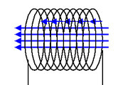
The circuit, described in this page, is a versatile circuit, which easily can be wired in many different configurations using at most two jumpers. When a magnet moves through a coil, then voltages are generated, which can be both negative and positive, depending on the orientation of the magnet and the direction of rate of change of the magnetic flux through the coil (for more theoretical background see here). The circuit allows
- full rectification, either with or without LED between the terminals
- two half-wave rectified signals, either with or without LED between the terminals
- signal, direct from the coil without any other component's load on the output
A diagram of the circuit is given below:
The circuit contains three switches S1, S2 and S3. These switches determine how the LED's are connected. There are four useful possible options:
- Demonstration of induction current with LED's: S1 and S2 are closed and S3 is left open.
- Demonstration of induction current with single LED: S1 and S2 are left open and S3 is closed.
- Use of half-wave rectified signal with external
circuitry, other half-wave going through LED:
- S1 is closed and S2 and S3 are left open.
- S2 is closed and S1 and S3 are left open.
- Use of external circuitry: All switches are left open.
There are more possible switch combinations, but these are not useful.
The first configuration is interesting for demonstrating that there are two possible polarities for the electromotive force, induced by moving a magnet through the coil. The second configuration demonstrates the concept of full wave rectification and nicely shows that when a magnet moves through the coil, that there are two flashes of light in a single LED.
The last configurations can be used with external circuitry connected to the tool. Both a fully rectified wave can be used or the signal directly from the coil. The full-wave rectifier does not introduce any load to the coil when all switches are left open and no external circuitry is connected between the terminals for the full wave rectified signal.
The diodes must be schottky diodes. A schottky diode has a much lower forward voltage drop than a normal silicon diode like the 1N4001. The forward voltage drop of the 1N5820 is only approximately 0.2 volts in this circuit, while the forward voltage drop of the 1N4001 is approximately 0.7 volts. Especially when the fully rectified signal is needed, then the total forward voltage drop in two normal diodes would be 1.4 volts, which strongly degrades the performance of the circuit. So, here is it really important to use schottky diodes for the rectifier circuit.
The LED's can be any type of LED as long as they have high light output at low current. Modern 5 mm white LED's and warm-white LED's are most suitable. They are incredibly bright, even at currents as low as 1 mA. White LED's can be purchased with a brightness of 15000 mcd or better at 20 mA. Green LED's also can be obtained at high brightness. Avoid UV-LED's or pink LED's, these only have a brightness in the order to 2000 mcd at 20 mA.
![]()
Construction of the demonstration tool
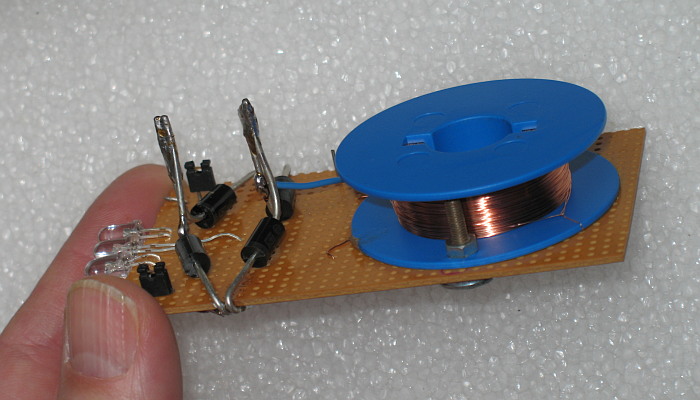
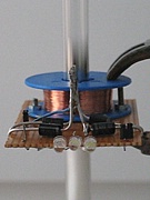
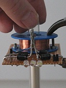
The construction of the demonstration tool is fairly straightforward. The tool must be constructed, such that it is robust and not easily damaged when held in your hand. Most vulnerable are the very thin wire connections to the winding on the spool. It is important that these are under the coil, when the coil is mounted on the printed circuit board. A picture from above shows how all components are attached to the printed circuit board.
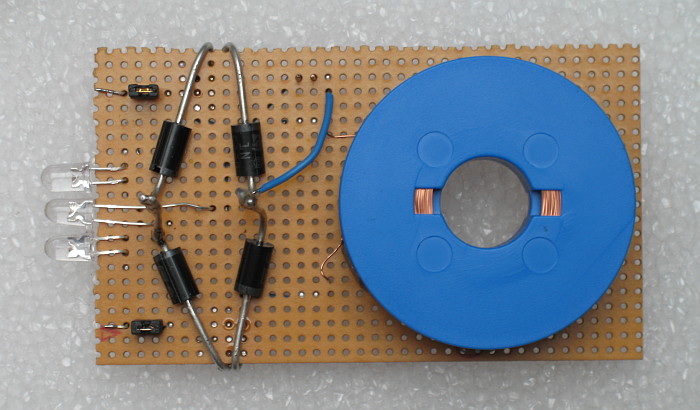
Three holes are drilled in the printed circuit board, one big hole, such that the magnet can be moved through the coil and two 3 mm size holes such that the spool can be connected to the printed circuit board with two bolts and corresponding nuts. Also two holes must be drilled in the spool. These are not visible in this picture but the picture at the start of the page shows how the spool is connected to the printed circuit board.
Drilling in the spool must be done with great care. The turns of thin copper wire are very vulnerable and one must be really careful not to touch these with the drill. Even a gentle touch certainly will destroy the coil!
Soldering the components on the printed circuit board is straightforward. The leads of the diodes were too thick to go through the holes in the printed circuit board. For this reason they were bent around the board and they were soldered with a lot of tin on many islands of the board in order to assure good structural strength.
The leads of the diodes also are used as terminals to which external circuitry can be connected. The leads are sturdy and with a crocodile clamp one easily can make a connection. Examples are shown below.
The switches of the circuit diagram are implemented by means of a few short leads, soldered through the printed circuit board. Closing the circuit can be done by placing a jumper over the leads. The picture shows two jumpers. In this picture, switches S1 and S2 are closed and switch S3 has no jumper on it (the two pins at the top-left of the blue wire). With the jumpers, a really low-cost solution is obtained. If all switches must be left open, then the jumpers just are placed over one lead instead of over a pair of leads, but they still can be kept on the board and hence are not easily lost.
![]()
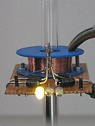
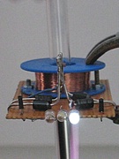
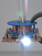
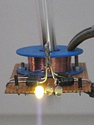
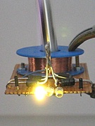
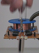
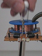
Tool in action: demonstration of polarity of induction current
A beautiful demonstration of the polarity of induction current can be given when switches S1 and S2 are closed and a magnet is moved through the coil. In that case, the circuit can be regarded as the following:
In this configuration there are two possible paths for current flow:
- Through the right schottky diode, through the left LED and then through S1.
- Through the left schottky diode, through the right LED and then through S2.
Which path is selected depends on the direction of the electromotive force, generated in the coil.
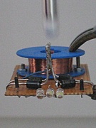
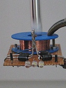
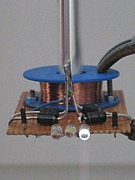
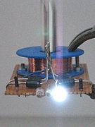
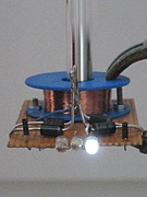
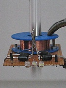
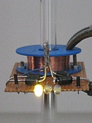
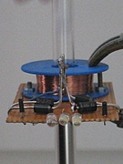
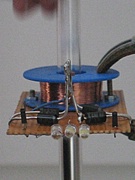
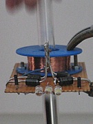
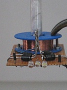
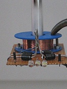
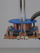
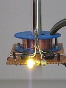
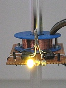
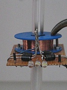
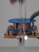
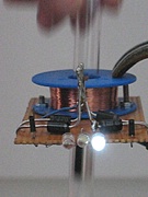
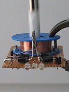
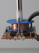
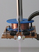
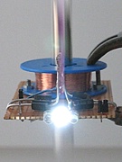
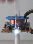
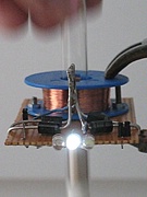
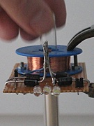
The sensitivity of the system is remarkably good. Just moving a medium-strength neodymium magnet through the coil produces a lot of electromotive force, enough the flash a LED brightly. The image sequence below shows how a tube with a neodymium magnet is moved downwards through the coil. When the magnet approaches the coil, then the white LED blinks. When the magnet is completely inside the coil (left picture from second row), then no LED blinks, and when the magnet is moving away from the coil downwards, then the warm-white/yellow LED blinks, until the magnet is too far away from the coil.
When the magnet is moved up, then again, first the white LED blinks and then the yellow LED blinks. The approaching magnet results in blinking of the white LED, a magnet moving away from the coil results in blinking of the yellow LED. This can easily be explained. Below and above the magnet, the field lines are pointing in the same direction. If the magnet approaches the coil, then the magnetic flux of field lines increases in the same direction, regardless of whether the magnet approaches from above or approaches from below.
A different situation can be achieved by turning the magnet upside down. This is done by simply turning the tube with the magnet upside down. When that is done and a magnet moves through the coil, then first the yellow LED blinks and then the white LED. This experiment nicely demonstrates that magnetic flux not only has a magnitude, but also a direction. When the direction of magnetic field lines is reversed, then the magnetic flux also reverses and when all else is kept the same, then of course the rate of change of magnetic flux also reverses sign.
Two videos are available for download. Both videos are similar, the difference is that in one video the tube with the magnet is inverted. This results in reverse ordering of the blinking patterns for the LED's. Both videos have a download size of approximately 5 MByte.
![]()
Tool in action: full wave rectified signal
When a fully rectified signal is used, then the center LED blinks when the magnet approaches the coil and the same LED blinks when the magnet moves away from the coil. The diagram for this configuration is shown here. Only switch S3 is closed, making the other two LED's effectively non-present. Current now always flows through the LED, regardless of polarity of the electromotive force.
This is demonstrated by the following 10 pictures where the tube with the magnet is moved from above through the coil. When the magnet is completely through the coil, then there is no light output and when the magnet is too far away from the coil there also is no light output.
Again, a video is made of this experiment. Now one can easily see the double blinking of the center LED when the magnet moves through the coil. Download size of this video also is approximately 5 MByte.
![]()
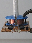
Tool in action: jumping magnet
This experiment is a nice demonstration of the reverse aspect of induction. A changing magnetic field induces an electromotive force, which can drive a current. On the other hand, a current induces a magnetic field around the wire through which the current flows. Using the demonstration tool, combined with a second coil, one can transform motion of a magnet into a current and that current then in turn can be used to create a magnetic field in the other coil. The setup for this experiment is really simple, once the demonstration tool is available.
A second spool with turns of copper wire is taken and a watch glass with a small neodymium magnet is put on the spool. The picture shows a small magnet with a diameter of just 2 mm and a thickness of 1 mm.
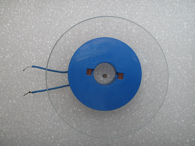
The spool is connected to the demonstration tool. The unmodified signal is taken from the tool in this experiment, but one also can take the fully rectified signal.
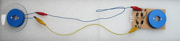
When a magnet is moved through the coil at the right then the small neodymium magnet jumps around in the watch glass. It is important that the wires between the two coils are sufficiently long, otherwise the small magnet may be influenced directly by the larger magnet. A video is made of the small jumping magnet. Each time when the magnet jumps, then the tube with the large magnet is moved through the coil on the demonstration tool. Click here for the video, its download size is 5.6 MByte.
![]()
Discussion of results
For more theoretical background on magnetic induction, see the page on induction. In this page, it is assumed that when a magnet is moved through the coil, then an electromotive force of the following time characteristic is produced:
Along the vertical axis, there is the electromotive force, expressed in volts and along the horizontal axis there is time. So, when a magnet moves through the coil, then first there is a positive electromotive force and then there is a negative electromotive force (or the other way around).
Characteristics of diodes
LED's and diodes are components, which only conduct current in one direction. Their characteristic (current as function of applied voltage) looks like the following:
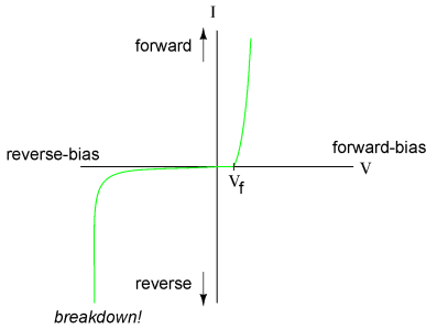
The voltage Vf is called the forward voltage drop. For the schottky diodes, used in this demonstration tool, this is approximately equal to 0.2 volts. For the LED's this forward voltage drop is somewhere between 2 and 3 volts. As long as the voltage in reverse direction does not exceed the breakdown voltage of the used diodes, then hardly any current flows in reverse direction. When the breakdown voltage is exceeded, then the diode might be damaged or even completely destroyed. So, the diodes can be regarded as components which only conduct current in one direction.
Full wave rectifier circuit
The full wave rectifier circuit with 4 diodes allows current to flow through the load for both a positive and negative applied voltage. Regardless of the sign of the applied voltage, the current always flows in the same direction through the load.
For a positive voltage the current flows through diode 1 and diode 2 and for a negative voltage the current flows through diode 3 and diode 4:
In a real-world application, part of the wave form is lost in the circuit, due to the forward voltage drop of the rectifier diodes. For this reason, schottky diodes are used in order to minimize loss of electromotive force due to forward voltage drop in the diodes.