

Power supply for electrolysis experiments
A large number of interesting experiments can be done with electrolysis. Electrolysis can also be used for making your own chemicals (e.g. making of metal salts from the metals, making of chlorates and bromates). When only small experiments are done, then any simple power supply can be used, but when more serious experiments are conducted, then a suitable power supply is a very nice addition to the home lab.
One can buy a good lab power supply, but a reasonable one, with sufficient power output and robustness has a certain price tag. A good lab power supply has a price of around $150, and besides this around $25 should be spent on wiring, clamps and so on.
A cheap, but very useful alternative is a PC power supply, together with a set of resistors for current control. A typical low-budget PC power supply has a price of $20 and one can also use one from an old PC. On this page, it is described how a PC power supply can be converted into a safe, easy to use and robust power supply for electrolysis purposes.
Virtually all electrolysis cells require a voltage between 2.5 V and 6 V for their operation, the majority even being between 4V and 5.5V. Only some exceptional electrolysis experiments require higher voltages, such as anodizing experiments. However, these usually only require very low currents. On this page, a 12 V power supply is described, which, combined with some carefully chosen resistors can be used to perform electrolysis experiments, which require large currents. A typical PC power supply allows at least 10 A of current from the 12 V wire.

Beware, when performing the steps, described on this page. Never modify anything inside a power supply, which is connected to the wall power outlet. Doing so may result in heavy shock and severe damage to health or even death. Also keep in mind that when the power supply is disconnected, there still may be considerable charge in capacitors, sufficient to give a strong electrical shock. It is strongly advised to start the modification process only on a power supply, which has been disconnected from the wall outlet for at least a few hours!
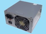
![]()
Converting the power supply to a 12 V supply
Open up the power supply. This usually can be done with a screwdriver and no other tools are needed. Be careful not to bend the case of the power supply too much and do not use extreme force to open up things. When the power supply is open, then something like the following can be seen:
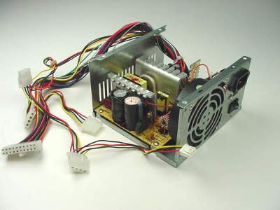
The two large electrolytic capacitors at the front are
high voltage capacitors. The power supply I opened up had two of them, both
rated at 560 μF and 200 V. When these are fully charged, they can give a really
nasty electrical shock, even when the device is unplugged.
![]() Be sure not to touch
these!
Be sure not to touch
these!
Inside a power supply, there are a lot of wires, which end at different connectors. Many of these wires occur multiple times, going to different connectors. They all are grouped and bundled at the same side of the printed circuit board. The following wires are present in a modern ATX power supply.
- orange: 3.3 V
- brown: 3.3 V sense
- yellow: 12 V
- blue: -12 V
- red: 5 V
- white: -5 V (not all ATX supplies have this)
- black: GND
- green: power-on
- grey: power OK indicator
- purple: 5 V standby
- Some newer power supplies also have yellow/black wires. This is a second 12 V rail, allowing higher total output at 12 V. Do not connect yellow/black and yellow wires, because these are separate rails, each rail having its own current sensing and overload protection. You can make two separate 12 V outputs by using the yellow wires and the yellow/black wires, each with its own connector and its own (optional) load. You can also simply cut the yellow/black wires if you do not intend to make two separate 12 V outputs. If you make a separate 12 V output with the yellow/black wires, then also add a second GND connector using the thick black wires, which are paired with the yellow/black wires. In this webpage, it is assumed that these yellow/black wires are not used.
Usually there will be a lot of wires in the power supply, most of these can be cut, close to the printed circuit board, in such a way that no short-circuit can be created.
The following wires must be kept. Initially, keep a length of approximately 20 cm (8 inches).
- 6 black wires
- 1 red wire
- 1 orange wire
- 1 brown wire (usually there only is one brown wire)
- 4 yellow wires
- 1 green wire (usually there only is one green wire)
So, most of the voltages are not used, only the 12 V is interesting. If you think that the 5 V is interesting as well, then also three red wires should be kept, but the power supply, described here, only has the 12 V output. For electrolysis experiments, a fixed 5 V output is not that interesting, because of lack of flexibility. The negative voltages also are not very interesting. They only allow a low current of a few hundreds of mA.
Next, perform the following steps:
- Connect the brown wire to the orange wire, by soldering the ends of these. Use a piece of shrink wrap (dutch: krimpkous) for covering the soldered ends. Be sure to wrap the shrinkwrap around one of the wires before the ends of the wires are soldered together. The shrink wrap assures that the soldered end cannot cause a short-circuit inside the case.
- In a similar way, connect the green wire with one black wire.
- Take another black wire and the red wire and connect a parallel circuit of two ceramic 22Ω/10W or 18Ω/10W power resistors between the red and black wire. The pair of resistors provides a load of around 10Ω and assures that the power supply powers up and it also assures good regulation of the output voltage. Attach the resistors to the inside of the case of the power supply using a cable-tie or tie-wrap at a place where there is some air-flow because these resistors become fairly hot, and assure that no short-circuit can occur with the case or electronics inside the power supply. Some websites propose using a single 10Ω/10W resistor, but this is not recommended. A single 10Ω/10W resistor becomes very hot, especially if there is not enough air flow.
- Take a third black wire and one yellow wire and connect a 560Ω resistor between the black and yellow wire. This provides a small load at 12 V. A nice visual effect is obtained, when the resistor is put in series with a high efficiency LED. In that case, use a 470Ω resistor. Again, use shrink wrap for covering all the blank wires and legs of the resistors and (optional) LED. If a LED is used, assure that it is connected at the right polarity. The longest leg is the anode and that must be connected to the yellow wire. The resistor must be rated for at least 0.25 Watt power consumption.
- Drill two holes in the top part of the case of the power supply and connect the output connectors to this part of the case. Assure that the output connectors are well isolated from the case! When buying such connectors, ask for an isolated version of these connectors!
- Now, you are left with three yellow wires and three black wires. These must be connected to the output connectors. Three wires are used in order to allow larger currents to be drawn without voltage drop. Just hook up the three black wires to the output connected for GND and hook up the three yellow wires to the output connected for 12 V.
- Next, close the case and you have a power supply, with 12 V output.
The resulting power supply looks as follows:
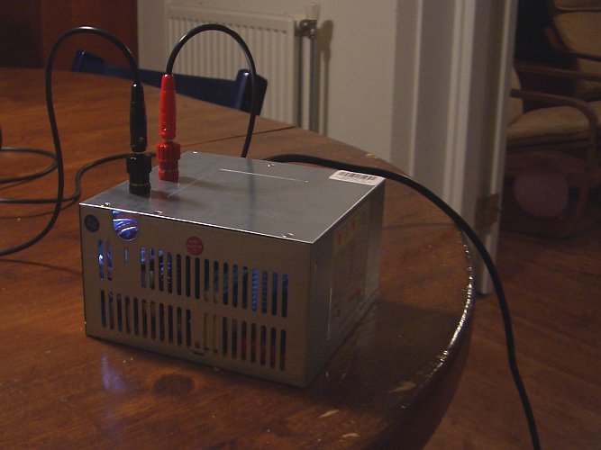
Inside, one can see the light of the LED, which is connected in series with the load-resistor of 470Ω. The red connector is +12 V and the black connector is GND. The PSU has its own short-circuit protection (it shuts down immediately, when the outputs are short-circuited), but in the sequel it is described how an external protection can be provided. Having the short-circuit protection of the PSU to work frequently may result in damage of the PSU, so it is better not to short-circuit it. If a short-circuit occurs, then disconnect the PSU from the mains and wait for at least a minute. It might take well over a minute before it can be used again after a short-circuit!
Total cost of this modification is around $10. The following items were needed:
- 1 red output connector
- 1 black output connector
- 2 ceramic power resistors, 22Ω / 10 Watt
- 1 resistor 470Ω or 560Ω, at least 0.25 Watt
- a few inches of shrink wrap
- optionally 1 LED (I used a white LED, any color is suitable).
All these items can be purchased at an electronics parts shop, such as Radio Shack or Conrad, but also locally in most towns.
![]()
Additional wiring and resistor networks
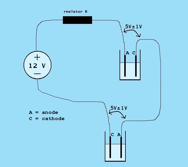
With the power supply alone, one does not perform electrolysis normally. Applying 12 V to a concentrated solution of an electrolyte usually results in excessive current and formation of unwanted products. It also results in excessive erosion of graphite anodes. Electrolysis at a constant voltage is not a good idea anyway. During the electrolysis process, the properties of the liquid change and the needed voltage changes. For this reason, one should have current control. The ideal situation would be to use a current source, but a much simpler solution, using a resistor also is suitable. It is safe to assume that the average electrolysis experiment requires 5 V � 1 V across the electrolysis cell. If the output of the voltage source equals 12 V, then the difference between the voltage source and the voltage across the electrolysis cell is 7 V � 1 V.
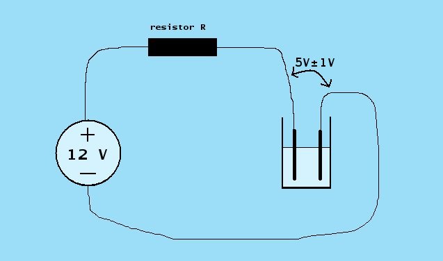
The normal circuit for electrolysis with this setup is shown in the diagram above. The presence of the resistor causes the voltage across the electrolysis cell to adjust itself to a voltage around 5 V, provided the concentration of the electrolyte is sufficiently high.
The resistor R determines the current, drawn by the cell and this is a powerful way of controlling the current. If a voltage of 7 V across the resistor is assumed, then the error in the computation will not be more than 15% in normal cases. This is perfectly suitable for the purpose of electrolysis.
The resistor R will dissipate quite some power, so one should use power-resistors for this. Using a set of single resistors (e.g. 8 Ω, 4 Ω, 2 Ω) is not feasible. That would require resistors, which allow dissipation of huge amounts of energy. Such resistors are very expensive. Below, a setup, suitable for almost any electrolysis experiment, is proposed, using cheap ceramic power resistors only.
Five resistors are made from commercially available cheap ceramic resistors:
- 3 resistors of 2.35Ω / 20W, each made from two 4.7Ω / 10W resistors
- 2 resistors of 5.5Ω / 20W, each made from four 22Ω / 5W resistors
The 2.35Ω resistors are made by taking two 4.7Ω resistors and wiring these in parallel. The 5.5Ω resistors are made by taking four 22Ω resistors and wiring these in parallel. Wires are connected to the resistors in order to make them easily pluggable. A close-up of one of the 2.35Ω resistors is shown here:
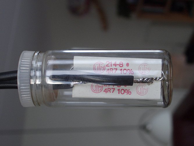
For safety reasons, the resistors are put in a small glass vial. This is not necessary, but it reduces the risk of accidental short-circuiting the power supply. Without the vial, the blank pieces of metal can easily come in contact with other resistors and cables. The resistors also can become quite hot and with these vials around them, the chance of accidentally picking up a very hot resistor is reduced. The ceramic resistors themselves tolerate very high temperatures, but of course, they can do harm to other things, which are touched by them.
The total setup is shown in the picture below. It shows the modified power supply (excluding the power cord for the wall outlet), the three 2.35Ω resistors and the two 5.5Ω resistors. Besides that, it shows three additional wires and some crocodile-clamps, which makes setup of electrolysis experiments easier.
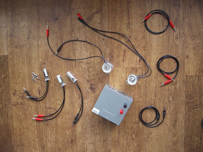
The total cost for all additional resistors and wires was approximately $30. Of course, when one does not need all of these, the cost can be reduced accordingly. E.g., using the three 2.35Ω resistors only, and using a single additional wire, the additional cost is reduced to $15.
The picture below shows a typical setup, used with the three 2.35Ω resistors in series, driving a tungsten incandescent bulb (the bulb representing the electrolysis cell). There are 5 volts across the bulb, leaving 7 volts for the three resistors. In this setup, a current of approximately 1A is flowing through the circuit, which is nice for electrolysis purposes.
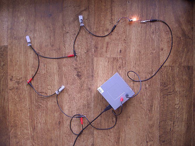
The three 2.35Ω resistors always must be in a series circuit, when they are inside a vial, otherwise they become too hot. So, with these three resistors, one only has access to approximately 1A of cell current. By spending the extra $15 for the other resistors and wires, one adds much more flexibility, but whether this is done or not depends on one's needs and one's budget. When the resistors are not put in vials, then one can use a series connection of just two of them, allowing a current of approximately 1.5A, but in this case one must be careful not to touch the very hot resistors and one must be more careful in setting up the experiment, in order to avoid short-circuit.
![]()
Achievable cell currents with the five resistors
In this section, resistors are switched in parallel and
in series. A series connection of resistors is represented by a +, a parallel
connection of resistors is represented by a //. Below, some resistor networks
are shown and below that, the expressions, representing the networks are shown.
- The top network is written as (5.5 // 5.5) + 2.35 + 2.35.
- The middle network is written as (2.35 + 2.35 + 2.35) // (5.5 + 5.5).
- The bottom network is written as 2.35 + 2.35 + 2.35.
The following networks are most interesting. These all can be used without the need to worry about overheating of the resistors:
- 5.5 + 5.5 + 2.35 + 2.35 Ω ==> Current approximately 0.4 A
- 5.5 + 5.5 Ω ==> Current approximately 0.6 A
- (5.5 // 5.5) + 2.35 + 2.35 Ω ==> Current approximately 0.8 A
- 2.35 + 2.35 + 2.35 Ω ==> Current approximately 1 A
- (5.5+5.5) // (2.35+2.35+2.35) Ω ==> Current approximately 1.7 A
When the 2.35 Ω resistors are not put inside a vial, then the following networks may be used (be careful here, not to have accidental short circuit, and keep in mind that the resistors become hot):
- (2.35 + 2.35) // (5.5 + 5.5) Ω ==> Current approximately 2.2 A
- (2.35 // 2.35) + (2.35 // 5.5 // 5.5) ==> Current approximately 3 A
All these examples show how versatile a setup with just 5 resistors is. This setup allows most electrolysis experiments to be performed without any problems.
![]()
Series connection of two roughly identical electrolysis cells
The power supply, described here, has a total voltage output of around 12 V. The section above shows how this can be put to use, by using a set of power resistors, needed for limiting and controlling the electrolysis current.
Under certain conditions, where high output is important, a nice option is to use a series connection of two roughly identical electrolysis cells:
Now, again a series resistor R is needed to limit the current, but this series resistor must be much lower than in the situation with a single cell. The voltage across the resistor may become as low as 1 V, and hence, the resistor must be low. Now it is not possible anymore to predict the current precisely, when a known resistor value is given. One should try with one, two or three of the 2.35 Ω resistors in parallel.
 Instead.
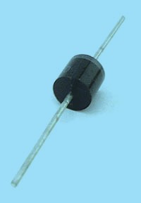
one now also could try with one or two normal silicon power diodes in series.
A suitable diode is the 6A100. This type of diode
allows 6A of current and is available in virtually every electronics parts shop
at low price. The picture at the left shows such a diode.
Instead.
one now also could try with one or two normal silicon power diodes in series.
A suitable diode is the 6A100. This type of diode
allows 6A of current and is available in virtually every electronics parts shop
at low price. The picture at the left shows such a diode.
It might even be possible to perform electrolysis without any limiting resistor or diode in series with the cell, but it is a matter of trial and error. It is advised to start off with a series resistor or two diodes in series and then try different configurations, until the desired current is flowing through the cells. Using this series connection of cells, one can have double useful output at the same current.
back to main miscellaneous page