


Electrolysis with special effects at cathode
A very popular chemistry experiment is the electrolysis of a table salt solution with copper wires or with graphite rods. This is the kind of experiments performed by many kids who make their first steps in the realm of (home-)chemistry. In almost all aqueous electrolysis experiments, hydrogen is formed at the cathode and some other product is formed at the anode. The same is true for the common high school electrolysis experiments. This may make people thinking that hydrogen always is formed at the cathode in aqueous electrolysis experiments. That things can be totally different is shown by a series of experiments in this webpage. Here, a set of electrolysis experiments is presented which shows interesting effects at the cathode, while at the anode only some gas is produced.
A common effect is the reduction of oxo-anions at the cathode, leading to formation of interesting products at the cathode. Sometimes this leads to formation of the element on which the ion is based, in other cases, interesting complexes are formed. In all cases, this is due to the strong reducing properties of the cathode. This set of experiments shows that electrolysis can provide an extremely strong "reductor".
Multiple experiments are presented in this page, but none of the experiments depends on the outcome or the chemical results of a previous experiment. So, if not all mentioned chemicals are available, then one can do part of the experiments.
Finally, a nice but funny experiment is given. It just makes use of phenolphtalein as pH indicator and shows the formation of hydroxide ion at the cathode when a solution of table salt is electrolysed.
![]()
![]() Required
chemicals:
Required
chemicals:
-
hydrochloric acid + sodium molybdate (or sodium hydroxide + molybdenum trioxide)
-
sulphuric acid + potassium iodate
-
sulphuric acid + sodium selenite
-
sulphuric acid + sodium bromate
-
sulphuric acid + sodium sulfite (or metabisulfite)
![]() Required
equipment:
Required
equipment:
-
small U-tube, one can also use a flexible transparent PVC tube and bend this into a U-shape.
-
platinum wires or thin graphite rods
-
power supply 12 V DC plus series resistor for current limiting
![]() Safety:
Safety:
- Selenites are very toxic. At any cost avoid exposure to this chemical.
- Sodium bromate is a strong oxidizer, but its use in this experiment does not introduce any risk of fire or explosion.
- Hydrochloric acid and dilute sulphuric acid are corrosive. If acid is spilled on the skin, then quickly rinse with a lot of water.
![]() Disposal:
Disposal:
- The waste of all experiments, except the molybdenum and the selenite, can be flushed down the drain. Molybdate and selenite waste must be brought to a municipal waste processing facility.
![]()
General setup for all experiments
All experiments use the same setup with a 12V DC power supply, a small U-tube and two platinum wires.
The power supply is connected to the U-tube through a series resistor. This series resistor has a value of approximately 7 Ω. This limits the total current to roughly 1 A (assuming that the cell voltage will be something around 5 V). With this setup, the electrolysis runs at nice speed without ever becoming too violent or running too hot. The resistor is built up from a set of ceramic power resistors. It is important that power resistors are used, otherwise the resistors will become very hot and may burn out.
Once all wiring is connected, the power supply is switched on and the system is allowed to do its work for a few minutes. By using a U-tube, the liquid around the anode is not quickly mixed with the liquid around the cathode. This allows one to study the changes around both electrodes with not too much interference.
![]()
Experiment 1: Formation of low oxidation state molybdenum complex
In this experiment, a solution of a molybdate in moderately concentrated hydrochloric acid is electrolysed. The total setup for the experiment is made as follows:
- Add a spatula full of solid molybdenum oxide or sodium molybdate to 7 ml of water.
- Add granules of sodium hydroxide, until all of the solid has dissolved. If sodium molybdate is used, then only a small amount of sodium hydroxide is needed, otherwise a little more is needed. Do not add too much, just add as much as is needed to dissolve the solid molybdenum compound.
- Add approximately 10 ml of concentrated hydrochloric acid (30% HCl by weight) and mix this with the solution. It might be that the liquid becomes somewhat turbid again, when this is done. Allow the solid matter to settle (this may take a few hours) and decant as much as possible of the clear liquid above the solid matter.
- Pour the clear solution in the U-tube.
- Put the electrodes in the U-tube and connect to the power supply and series resistor(s).
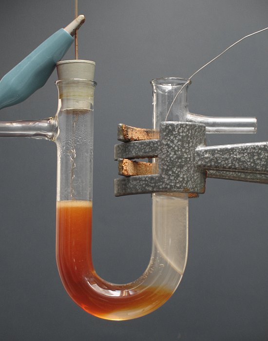
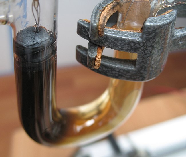
When power is switched on, then at the anode a gas is produced (mainly chlorine gas: smell!!). At the cathode, a remarkable yellow color is produced. After a longer time, the liquid around the cathode becomes deep red/brown. Also a colorless gas is produced at the cathode.
The picture shows the result of the electrolysis when it runs for several minutes. A nice effect is that the red liquid tends to move towards the anode. This is due to the fairly strong formation of gas bubbles at the anode and these tend to 'stir' the liquid somewhat. But as soon as the red liquid comes close to the anode, then the red color disappears at once.
Three videos are present of this experiment:
- Electrolysis, immediately after switching on the power supply: molybdate in HCl
- Electrolysis, some time later: molybdate in HCl, continued
- High speed (3 times) video of electrolysis process: molybdate in HCl, 3-speed
Download size of these videos is around 3 MByte each.
![]()
Experiment 2: Formation of iodine from iodic acid
In this experiment, a solution of potassium iodate in dilute sulphuric acid is electrolysed. The experimental setup is as follows:
- Add a spatula full of solid potassium iodate to 15 ml of dilute sulphuric acid (10% by weight). Dissolve all of the solid. Instead of potassium iodate, one can also use potassium hydrogen diiodate, iodic acid or sodium iodate.
- Pour the clear solution in the U-tube.
- Put the electrodes in the U-tube and connect to the power supply and series resistor(s).
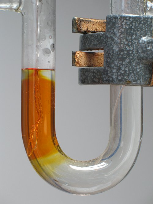
When power is switched on, then a colorless gas is produced at the anode. This colorless gas is oxygen. At the cathode, a fine dispersion of solid iodine is formed, together with some hydrogen gas. The iodine really separates as a solid and does not dissolve in the liquid (this is in strong contract with electrolysis of a solution of potassium iodide where iodine is formed at the anode and goes in solution as tri-iodide). After some time, a thick layer of dark grey foam is produced.
The picture below shows a close-up of the foam of iodine.
In this electrolysis experiment one also can see that the liquid at the bottom of the U-tube is not mixed with the liquid above it. Around the anode, the color of the liquid also slowly changes from colorless to brown, due to mixing of the liquid. The bubbles of gas, formed at the electrodes cause slow mixing of the liquid.
Again, some videos are made of this electrolysis experiment:
- Electrolysis, immediately after switching on the power supply: iodate in sulphuric acid
- High speed (4 times) video of electrolysis process: iodate in sulphuric acid, 4-speed
Download size of these videos is around 3.5 MByte each.
![]()
Experiment 3: Formation of bromine from bromic acid
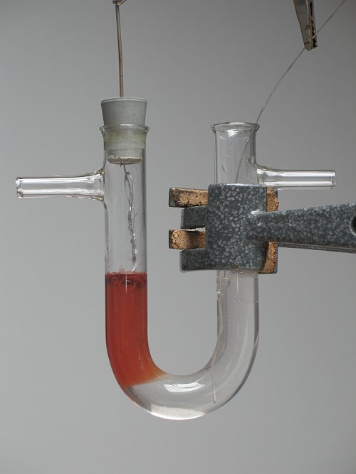
This experiment is very much like the one above. Instead of iodate, bromate is used. A spatula full of sodium bromate is dissolved in 20 ml of dilute sulphuric acid (10% by weight). This solution then is electrolysed. When power is switched on, then a colorless gas is produced at the anode. This gas is oxygen. At the cathode hardly any gas is produced, much less than in the experiment with the iodate. Bromine slowly spreads through the liquid around the cathode.
Two videos of this electrolysis experiment can be downloaded here:
- Electrolysis, immediately after switching on the power supply: bromate in sulphuric acid
- High speed (4 times) video of electrolysis process: bromate in sulphuric acid, 3-speed
Download size of first video is 3.2 MByte, download size of second video is 4.3 MByte.
![]()
Experiment 4: Formation of selenium from selenous acid
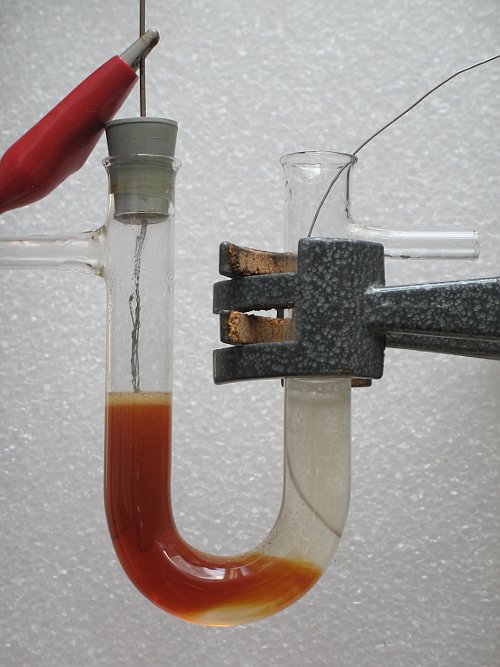
Selenium in the form of selenite also can be converted to the element by means of electrolysis. Again, the element is formed at the cathode. In this experiment, a spatula full of sodium selenite is dissolved in approximately 20 ml of dilute sulphuric acid (10% by weight) and then electrolysed (selenous acid or selenium dioxide also can be used). As expected, at the anode a colorless gas is produced, this is oxygen. At the cathode, bright orange/red solid selenium is formed, together with hydrogen gas. A brick-red foam of wet selenium is formed in the cathode tube, similar to the formation of foam of iodine in the experiment with iodate.
Two videos of this electrolysis experiment can be downloaded here:
- Electrolysis, immediately after switching on the power supply: selenite in sulphuric acid
- High speed (4 times) video of electrolysis process: selenite in sulphuric acid, 3-speed
Download size of first video is 2.4 MByte, download size of second video is 3.7 MByte.
![]()
Experiment 5: Formation of sulphur from sulphurous acid/sulphur dioxide
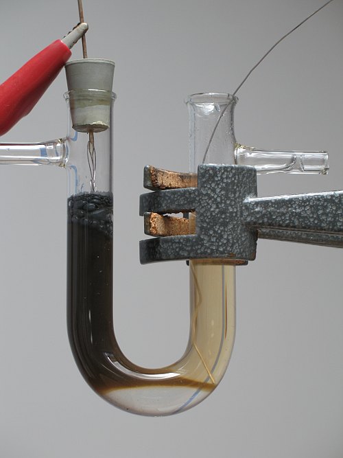
Even the well-known sulfite or sulphur dioxide can be reduced to elemental sulphur by electrolysis. A spatula full of potassium metabisulfite or sodium sulfite is dissolved in approximately 20 ml of dilute sulphuric acid (10% by weight) and then electrolysed. At the anode a colorless gas is produced, this is oxygen. It is remarkable that oxygen is formed at the anode, apparently the sulfite is not oxidized to sulfate or only to a minor extent. At the cathode only a small amount of gas is produced and the liquid quickly becomes cloudy around the cathode. After a few minutes the liquid around the cathode is completely turbid and light yellow.
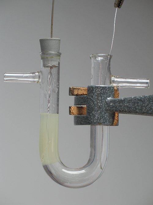
After a while, there also is a very strong smell of rotten eggs. So, part of the sulfite is reduced to hydrogen sulfide. This is in contrast with the selenite, where there is no smell at all from the cathode area.
One video is made of this reaction: sulfite in sulphuric acid. Download size of this video is 5.2 MByte.
![]()
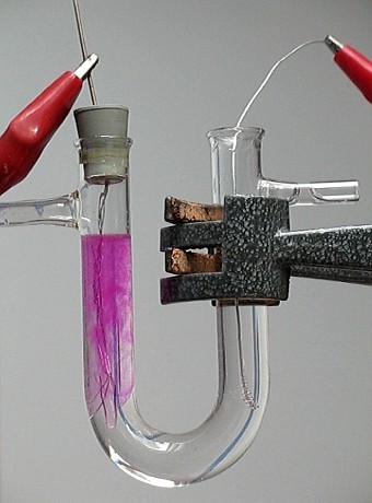
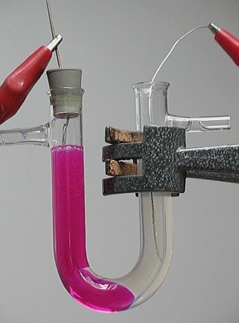
Experiment 6: Fun with table salt and phenolphtalein indicator
This experiment is not of the same kind as the other, it is a classical electrolysis experiment, being electrolysis of a solution of table salt. To this solution, a few drops of phenolphtalein indicator solution are added. When such a solution is electrolysed, then a fairly spectacular change of color occurs as soon as the power supply is switched on. The left picture shows the situation just a few seconds after switching on the power supply, the right picture shows the situation a few minutes later.
Two videos of this electrolysis experiment can be downloaded here:
- Electrolysis, immediately after switching on the power supply: phenolphtalein_in_NaCl
- High speed (4 times) video of electrolysis process: phenolphtalein_in_NaCl, 6-speed
Download size of first video is 1.8 MByte, download size of second video is 3.7 MByte.
![]()
Discussion of results
![]() In the first 5 experiments, the interesting effects at the cathode are due to
reduction of an anionic species by means of the cathode. Despite the negative
charge of the anions, they still can be reduced by the strongly reducing
cathode. It probably is true that the reduction is not a direct reduction at the
cathode, but that as intermediate species atomic hydrogen is involved. The
reactions then proceed as follows:
In the first 5 experiments, the interesting effects at the cathode are due to
reduction of an anionic species by means of the cathode. Despite the negative
charge of the anions, they still can be reduced by the strongly reducing
cathode. It probably is true that the reduction is not a direct reduction at the
cathode, but that as intermediate species atomic hydrogen is involved. The
reactions then proceed as follows:
H+ + e → HÀ
One reaction is formation of hydrogen gas bubbles: 2HÀ → H2
The other reaction is reduction of the acid, based on the added anionic species. For iodate, bromate, selenite and sulfite this translates to reduction of iodic acid, bromic acid, selenous acid and sulphurous acid to the element or even to the iodide, bromide, selenide and sulfide, which with excess of the acid of the anionic species gives the free element.
![]() For added iodate and selenite the reaction is as
follows:
For added iodate and selenite the reaction is as
follows:
HIO3 + 6HÀ → H+ + Iû + 3H2O
H2SeO3 + 6HÀ → H2Se + 3H2O
For bromate and sulfite the reactions are completely analogous.
![]() With excess iodate/iodic acid, the iodide gives iodine
in the strongly acidic solution:
With excess iodate/iodic acid, the iodide gives iodine
in the strongly acidic solution:
5Iû + HIO3 + 5H+ → 3I2 + 3H2O
With excess selenite/selenous acid a similar reaction occurs:
2H2Se + H2SeO3 → 3Se + 3H2O
For the bromate the reaction is completely analogous to the reaction of the iodate. For the sulfite this also is true, but reaction of hydrogen sulfide with sulphurous acid is not as fast as the reaction between hydrogen selenide and selenous acid. So, some of the H2S makes it to the surface and can escape as gas. This explains the smell of rotten eggs in the experiment with sulfite.
In the reactions with iodate and bromate, the iodide and bromide completely remain in solution and hence all of it reacts with excess iodic acid/bromic acid to the free halogen.
![]() With the molybdate the situation is even more involved. In the strongly acidic
solution, the molybdenum most likely is present as some oxo-chloro complex of
molybdenum(VI) or just as oxo-complex of molybdenum(VI), e.g. H2MoO4
and/or HMoO3Cl or even MoO2Cl2. Such species
are reduced to a molybdenum(III) species, which gives a red/brown complex with
the chloride ions in the solution. Unfortunately no precise balanced equations
can be given. The complexes involved in the molybdenum case are not
well-specified and are not fully understood. What is known though is that
molybdenum is reduced from oxidation state +6 to oxidation state +3.
With the molybdate the situation is even more involved. In the strongly acidic
solution, the molybdenum most likely is present as some oxo-chloro complex of
molybdenum(VI) or just as oxo-complex of molybdenum(VI), e.g. H2MoO4
and/or HMoO3Cl or even MoO2Cl2. Such species
are reduced to a molybdenum(III) species, which gives a red/brown complex with
the chloride ions in the solution. Unfortunately no precise balanced equations
can be given. The complexes involved in the molybdenum case are not
well-specified and are not fully understood. What is known though is that
molybdenum is reduced from oxidation state +6 to oxidation state +3.
The solution with the molybdenum in oxidation state +3 is strongly reducing and as soon as some of this comes near the anode, then it immediately is reoxidized to colorless molybdenum(VI), either by the anode, or by chlorine formed at the anode in the HCl-solution.
![]() Finally, the reaction with the phenolphtalein is just according to the classical
electrolysis experiment. At the anode, chloride ion is oxidized to chlorine gas,
at the cathode, water is reduced to hydrogen gas and hydroxide ion. The
hydroxide ion in turn gives the pink/red color to the phenolphtalein, which is
colorless below pH = 8 and beautifully pink/red above pH = 10.
Finally, the reaction with the phenolphtalein is just according to the classical
electrolysis experiment. At the anode, chloride ion is oxidized to chlorine gas,
at the cathode, water is reduced to hydrogen gas and hydroxide ion. The
hydroxide ion in turn gives the pink/red color to the phenolphtalein, which is
colorless below pH = 8 and beautifully pink/red above pH = 10.