

High voltage power supply
This page describes, how I have built a very flexible high voltage power supply, suitable for all kinds of experiments, ranging from simple neon-bulb experiments, requiring a few 100's of volts, to experiments, requiring 10000 V DC. This power supply provides both AC and DC signals, symmetric around two common GND lines. One is for a medium voltage GND, and all voltages in the order of magnitude of a few 100's of volts are relative to this. There also is a so-called HV GND (High Voltage ground), which is not connected to the medium voltage GND.
This power supply consists of two stages of voltage transformation. The first stage is from the mains to an isolated symmetric set of voltages around a common ground. Combining these voltages makes it possible to generate many different voltages in the 100's of volts range. These voltages in turn are used as input for a set of neon transformers to provide the real high voltage output. Neon transformers were used at only 50% to 60% of their rated input voltage. This is a loss of useful high voltage, but it makes the power supply really robust. Below, all details of this decision are explained.
This page is not a precise recipe, how to build a HV power supply yourself. Probably you will not be able to obtain precisely the same components as I had available. This page, however, is an attempt to describe my lines of thought and is an attempt to help you make your own design for a versatile HV power supply. The line of thinking, outlined in this page, certainly can be applied to other, similar situations.
![]()
Use of surplus parts, reducing cost
When the power supply needs to be built from new components only, specially purchased at values you want, then it becomes quite expensive. It is advised to check for surplus hardware suppliers or some cheap eBay supplier, who sells all kinds of transformers, capacitors and resistors. Using this strategy can save you a lot of money, but the drawback is that you usually have to do with the materials available and hence need to improvise more.
For the first stage, try to find a transformer with many taps, or a transformer with many secondary windings. If that is not possible, then buy multiple transformers, each having two identical secondary windings. I had access to a weird big toroidal transformer, with the following secondary windings:
- 2 x 70 V AC
- 2 x 30 V AC
- 2 x 20 V AC
- 2 x 20 V AC
- 1 x 40 V AC
Although the division of voltages of this transformer is not really ideal, I still decided to use this transformer, because I had lying it around for many years already. If you have to buy a transformer, or a set of transformers, then you could decide to use more evenly divided voltages. The transformers need not to be heavy duty parts. An output current of 500 mA per winding is more than ever is needed.
For the high voltage part, take neon transformers, capable of producing around 3000 volts at no-load and producing approximately 10 mA, when shortcircuited. Try to find 4 of these.
![]()
Medium voltage stage and mains isolation
This is the first stage of the power supply. It transforms the mains voltage to a whole bunch of AC voltages. With the transformer I had, I obtained the following voltages (two times, anti-phase): 70, 100, 120, 140 V AC. The secondary windings were connected as shown in the circuit diagram below. How things are setup in your configuration depends on the available transformers. Also keep in mind, that if separate transformers are used, then the secondary windings of all these separate transformers are not used next to each other, but in a mirror configuration, one winding in the positive phase section, and the other winding in the negative phase section.
Below follows the circuit diagram of the medium voltage section, I made from the big transformer. Each big ● is a terminal, connected to a plug on the outside of the box and is available for connecting external wiring or experimental circuits.
In this way, four different symmetric AC voltages can be obtained. The single 40 V AC winding was not used in this part of the power supply, but it came in handy, when designing the HV-part of the power supply.
I also had lying around a lot of 220 μF / 400 V electrolytic capacitors (purchased from eBay, as a surplus lot of 50, for only $40 + shipping, for all 50 of them). I took 6 of these to make two 660 μF capacitors and wired these up to make a symmetric DC rectifier and ripple suppression filter for voltages up to �200 V DC. These medium voltages are very useful for experiments with neon bulbs, xenon stroboscopes and nixies. The 6A100 diodes were also purchased from eBay, a lot of 50 pieces for $15 + shipping. The resistors of 2.2 MΩ are bleeder resistors, which slowly discharge the capacitors, when the power supply is unplugged. When these are not used, then there could remain a dangerous charge on the capacitors for a very long time. Any value of 1 to 5 MΩ is suitable, just look what you can obtain easily or have still lying around, but please don't omit these.
The DC rectifying and filtering circuit is not connected in a fixed way to the AC voltages, but the diode terminals are left open and a plug is made for them on the outside of the box. By means of external wiring (dotted lines in the diagram above) this allows me to select any of the following DC voltages: �100, �140, �170, �200. The circuit also allows for asymmetric DC voltages, e.g. +200 V and -140 V.
![]()
High voltage stage
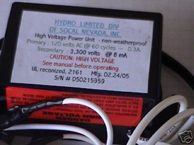
This is the trickiest part of the power supply. How this must be set up, strongly depends on what you can find. I used four high voltage transformers, so-called Neon Sign Transformers (NST's). These NST's sometimes can be obtained cheaply. I had two transformers of 3150 volt at no load, 9 mA at shortcircuit, for only $10 each. These are made for the European market, accepting 230 V AC. I had another pair of transformers for 120 V AC input, producing 3300 V AC at no load, and producing 8 mA current, at shortcircuited output. These also were from eBay, at a price of $30 per unit.
A neon sign transformer is a special type of transformer, intended to be used with a load always. When it has no load, then it has high voltage, which is good for initial firing up of a load, consisting of gas discharge tubes. When the current increases, then the output voltage drops, without the transformer heating up excessively. This type of transformers also is very nice for a HV power supply. You do not need (nor want) a very stiff and tightly regulated high voltage power supply.
If a neon transformer has no load, then it can have problems with its internal high voltage insulation and it can produce stray magnetic fields, which can cause considerable internal heating up of the device. Many neon transformers cannot stand long term open circuit, when their input is at the rated voltage. On the other hand, neon transformers also should not be used with a complete shortcircuit of their output leads, that also can lead to considerable heating of the device. When a neon transformer is operated at only 50% to 60% of its rated input voltage, then it can be used with any load between full shortcircuit and total no-load situation for any length of time. That is an important property for an experimental power supply. One does not want a power supply, which self destructs after an hour usage with the wrong load.
Below follows an explanation of what I did, with the voltages I had available. One probably cannot precisely reproduce this particular setup, but the line of reasoning can be followed and adapted to one's available transformers.
I decided, I want symmetric HV voltages between appr. 500 V AC and 4000 V AC (one side). By combining both anti-phase sides, 1000 V AC to 8000 V AC at no-load condition can be obtained in this way. I also did not want to use the neon transformers much above 50% of their rating, for the above reasons.
This could be accomplished by means of the following circuit:
The two neon transformers, which require 230 V AC input are connected to the medium voltage GND at one side and the other side is left open, and a plug for that is available at the outside of the box. By means of external wiring, it can be connected to one of the 70, 100, 120 or 140 V AC outputs. This allows for a HV output of 1000 V, 1350 V, 1650 V or 1900 V, either in-phase or anti-phase (by connecting to the medium AC voltage outputs of opposite phase). Any sum, or difference between these voltages then can be generated at the HV-side. These terminals are connected to the outside of the box.
At this point, the 40 V AC winding of the toroidal transformer came in handy. It was combined with another cheap 30 V transformer, making a total of 70 V AC. I connected this voltage to the 120 V AC neon transformers, both transformers were connected, but in such a way that their outputs are in anti-phase. Each of these transformers yields almost 2000 V AC. One of these is placed in series with one 230 V AC transformer output and the other is placed in series with the other 230 V AC transformer output.
This configuration then allows for voltages (purely symmetric) of 2000 � 1000, 2000 � 1350, 2000 � 1650 and 2000 � 1900 V. Voltages are additive, when in phase, subtractive, when out of phase. The terminals on the outside of the box are made such, that if the external wiring remains on the same side, then voltages add up, if the external wiring is connected in a cross-over way, then voltages subtract. This allows for a large range of symmetric AC voltages.
Besides the AC-outputs, a rectifier circuit was added as well, using 20 mA / 20 kV high voltage diodes. Using these, rectified unfiltered output is available on a second set of HV terminals. Inside the power supply, also a pair of capacitors, together with a bleeder resistor, is built in. This can be connected to the rectified outputs, making a DC power supply of several kV. This DC power supply can be used to power certain components, such as HeNe laser tubes. It also can be used nicely to power Marx generators for very high voltage pulses and big sparks. The AC power output can be used in conjunction with a Cockcroft Walton multiplier to obtain very high voltage output, nice for experiments with sparks and high static discharges.
The capacitors were built, by connecting 18 capacitors, each 220 μF / 400 V in series, and a resistor of 2.2 MΩ in parallel to each capacitor as equalizing and bleeder resistors. More info on this is given below.
![]()
Physical buildup of the power supply
All components in the power supply are covered here in more detail, and it is shown how all these are connected together and built into a box.
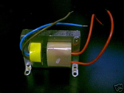
Neon transformers
The neon transformers were obtained from eBay. The transformer, shown at the left is the transformer, requiring 230 V AC input, the other one requires 120 V AC input at normal operation. The top one was purchased for $10 per item and the other one for $30 per item. The last one is a nice compact transformer, which can easily be mounted in any case. Of each type, two pieces were purchased from eBay.
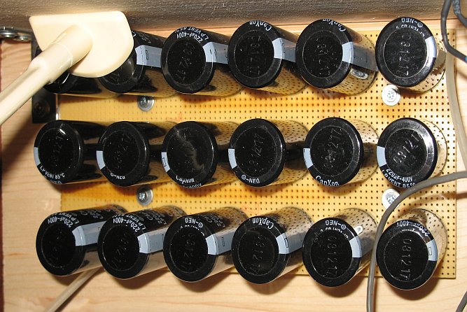
Home-made high voltage capacitors
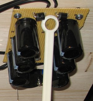
The high voltage capacitors were built on a prototyping board, with pre-etched patterns and pre-drilled holes in it. Each high voltage capacitor is made from 18 electrolytic capacitors, 220 μF / 400 V, connected in series, and a resistor of 2.2 MΩ in parallel to each capacitor. All capacitors are connected as follows on the board:
The capacitors are connected in series (they are so-called snap-in type capacitors, with two short legs, connected on one side of the cylindrical case). The holes for the legs of the capacitors had to be made a little larger. Resistors were soldered on the other side of the board, between the two legs of each the capacitors. If a prototype board is used, with copper patterns on it, then it is very important, to etch away strips of copper, as shown in the picture above. Otherwise, a big and really destructive spark may be formed between the first and 12-th capacitor in the series and the 7-th and 18-th (between these there may be a voltage difference of ⅔ of the total voltage difference between the two end-terminals of the capacitor). Below follows a picture of how this looks in reality. One can vaguely see the effect of the etching on the color of the prototype board, it has become a little darker and somewhat more orange/brown instead of yellow brown. The etching was done with 50% nitric acid, but it can also be done with a mix of hydrochloric acid and hydrogen peroxide. This must be done, before the capacitors and resistors are soldered on the board.
Two of these high voltage capacitors were made, and these two together can be used to make a symmetric high voltage DC power supply.
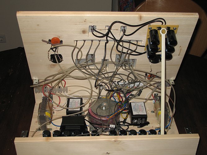
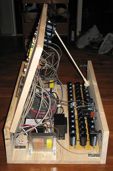
Box, in which all components are built
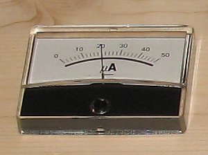
All components (transformers, capacitors and resistors) are built into a wooden box. All wiring at the mains and also the medium voltages is plain wire, used in normal electrical installations, with insulation, suitable for 230 V AC. All wiring at the HV-side is done with special high-voltage wire, which can withstand very high voltages before the insulation breaks down. Also, all boards, and also all components, except the transformers, are connected to the wooden box by means of small busses, which allow an insulating distance of 1 cm between the box and the PCB/component. In this way, not a single component can touch the wood of the box. Below, the box is shown, with its inside wiring and components. The small picture at the upper right shows how the medium voltage capacitors are setup and how they are connected to the top side of the box. The small picture at the lower right shows a 50 μA meter, which is used to measure the output voltage of the series connection of a 230 V neon transformer and a 120 V neon transformer. This meter uses a rectified and filtered signal, derived directly from the HV AC outputs by means of a full wave bridge rectifier and a 4700 pF / 6300 V capacitor and a 140 MΩ resistor. Using that configuration, then for each 10 μA, one can read 1 kV of AC output (peak voltage then is approximately 1.4 kV). With two of these meters, one can actually read the HV output at the AC-terminals.
Finally, the box was closed and the end result is as shown in the following picture. At the sides, plastic plates are attached, with room for ventilation. At the top, all connectors are attached to a thick plastic plate, which is connected to the wood.
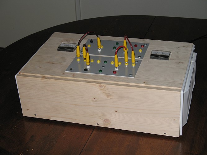
This picture also shows, how external wiring is used to select a certain HV-voltage and to select medium voltage DC.
The following picture shows, how each plug is connected internally. The colors have a certain meaning:
- yellow : AC output voltages
- red: DC voltage outputs, positive
- black: DC voltage outputs, negative
- green: GND (there are two GND's, one for HV and one for the medium voltages).
- white: AC inputs, accepting one of the medium AC voltage outputs.
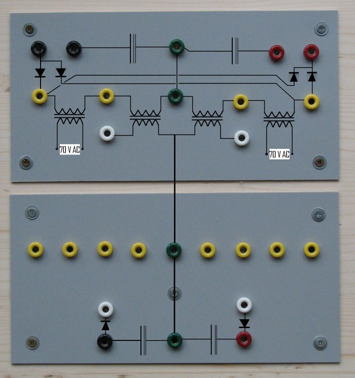
The capacitors are drawn without the bleeder resistors. The white connectors are used as input. The lower row of yellow connectors, with the green one in the middle are the 140, 120, 100, 70, GND, 70, 100, 120, 140 V AC outputs. These can be connected to the lower white plugs for obtaining filtered DC medium voltage. These voltages can also be connected to the upper white connectors. If that is done, then an AC voltage is added to the already fixed voltage of approximately 2000 V AC, which is made from the fixed 70 V AC.
Connecting wires between the two upper black connectors and the two upper red connectors allows the formation of a high voltage symmetric DC power supply, with a maximum of over 5000 V DC per capacitor. When a load of a few mA is attached, then the voltage drops considerably, but ripple rejection remains good with the built in capacitors (effective capacitance is 12 μF). One can also connect external capacitors at the raw rectified outputs (top right red connector and top left black connector). This power supply also is very good for charging capacitors in a controlled way, e.g. for pulse discharge capacitors. I have a big 40 uF / 6000 V capacitor, which can be charged to 5 kV within approximately 1 minute by this power supply, by connecting it between the top right red connector and the green HV GND connector.
Power supply in action
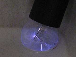
The power supply can do nice things. It can draw hot arcs for prolonged times of approximately 1 cm. It can also drive a small Jacob's ladder and also is capable of making strong ionization/plasma effects in ordinary incandescent tungsten bulbs. Some pictures of its action:
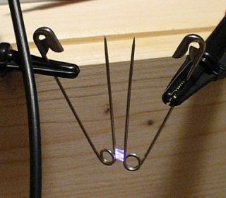

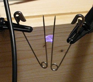
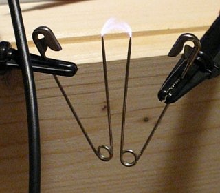
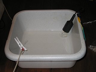
Below follows the result of applying 4 kV AC to a bulb, immersed with its glass top in slightly salted water, with the other electrode dipped in the water directly. Left is the circuit used, right is the result after switching on the power supply.
back to miscellaneous main page