
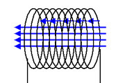

Changing magnetic fields -- induction currents
This experiment is a beautiful demonstration of the effect of induction. A changing magnetic flux through the area encircled by a closed path produces an electromotive force around that closed path, which can be applied to move electric charge along the closed path. When the closed path is covered by a conducting wire, then a current flows through the wire. When a cut is made in the wire, then the potential across the cut equals the electromotive force, which can be expressed in volts.
The beauty of this experiment is that the required setup for demonstrating the effect of induction is really simple while the effect is rather stunning. In 10 minutes the setup can be soldered and a demonstration of the effect can be given by simply moving a strong magnet through a coil, resulting in a strong flash of light.
![]()
Required equipment:
- A spool of copper wire with lacquer, normally used for making inductors or transformers.
- A high-efficiency LED, any color is suitable as long as it gives bright visible light.
- A standard silicon diode (e.g. 1N4001).
- Soldering tin and a soldering iron.
- A cylindrical neodymium magnet, 30 to 50 mm length, 8 to 10 mm diameter, having a pull strength of 3 to 5 kg on a steel plate.
- A tube in which the neodymium magnet can be moved and around which a coil can be made.
Safety:
- Neodymium magnets of the size used in this experiment are very strong and one has to be sure that it does not collide with high speed into other magnets or iron/steel objects. The magnet might be shattered into many small pieces and if a finger is hit by a colliding magnet, then this may be very painful.
![]()
Construction of a very simple generator
Making the generator is simple. A coil of thin copper wire must be connected to a LED and a normal silicon diode must be connected anti-parallel to the LED in order to protect it from too high voltage spikes. The following diagram shows the basic idea behind the generator used in this experiment.
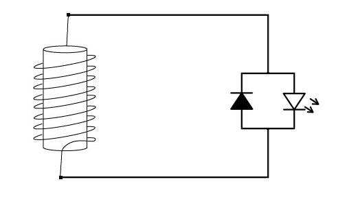
When the magnetic flux through the coil changes, then a certain voltage can be measured across the terminals of the coil. If that voltage is sufficiently high, then the forward voltage of the LED is exceeded and a current flows through the circuit, resulting in emission of light in the LED. A changing magnetic flux is created by moving a magnet through the coil, simply by letting is fall through the coil or by shaking a tube with a magnet inside, with the coil around the tube.
Type of magnet needed for the generator
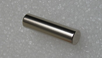 The
choice of the magnet is important. The magnet must be a neodymium magnet of
sufficient size, otherwise the effect is not strong enough to make a LED glow by
just letting a magnet fall through the coil. The magnet shown here is a
cylindrical magnet with a length of 40 mm and a diameter of 10 mm. It has a pull
strength of 4.3 kg on a thick steel plate. If no such rod is available, then it
also is possible to stack multiple disk-shaped magnets or ring-shaped magnets,
such that a cylinder is obtained. Even square or cubic magnets can be used by
stacking them, but of course these are less practical if a round tube is used.
The
choice of the magnet is important. The magnet must be a neodymium magnet of
sufficient size, otherwise the effect is not strong enough to make a LED glow by
just letting a magnet fall through the coil. The magnet shown here is a
cylindrical magnet with a length of 40 mm and a diameter of 10 mm. It has a pull
strength of 4.3 kg on a thick steel plate. If no such rod is available, then it
also is possible to stack multiple disk-shaped magnets or ring-shaped magnets,
such that a cylinder is obtained. Even square or cubic magnets can be used by
stacking them, but of course these are less practical if a round tube is used.
Construction of coil
A suitable coil can be made from very thin copper wire, having a special lacquer coating, such that it is isolated and can be wound into coils. Best results are obtained when a coil is made around a non-conducting tube made of PVC, plastic or glass which is smooth inside. A good starting point is to take 1500 turns in a single winding around a tube, through which a cylindrical magnet easily can be moved. The tube must have a length of approximately 20 cm and the winding must be in the middle of the tube, covering only a length of 2 cm, such that the magnet can be totally on one side of the winding or on the other side of the winding. The schematic drawing shows how the tube and coil have to be constructed. The schematic drawing only shows a few turns, in reality around 1500 turns should be used and these turns will form a winding of copper wire having a depth of several mm.

When no suitable equipment is available, then making a
winding of 1500 turns around a tube is a very tedious job, but it can be done of
course. For this reason an alternative construction is provided for the more
lazy people among us
![]() .
.
![]()
Alternative construction of a simple generator
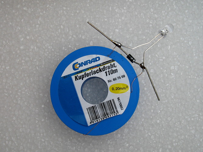
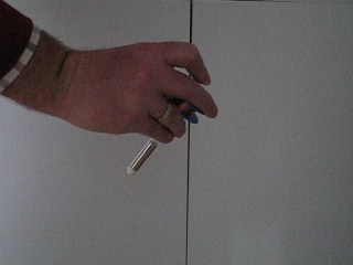
An alternative is to buy a spool of isolated copper wire, used for making coils or transformers. These spools usually are made of plastic and have copper wire wound around them very tightly and the two ends are available as well. To this you simply solder a diode and a LED, as shown in the diagram above. The spool shown below has 110 meters of wire in a single winding and the diameter of the turns is between 18 mm and 30 mm. This means that it has around 1450 turns. Even better results can be obtained with a spool having 0.10 mm wire, but this was not available to me when I did this experiment. Such spools can be purchased in electronics shops, but they also are available from online stores like Conrad.
When a magnet is dropped through the hole in this spool, then a voltage is induced across the LED.
This setup is not as easily used as a long tube, around which a spool is wound. You could simply drop a magnet through the hole from a distance of 10 cm, but that frequently results in the magnet falling on the spool and not going through the hole. Best is to find a thin-walled tube, which just fits through the hole and then use a magnet, which just fits the tube. Any material can be used for the tube, as long as the magnet can move smoothly inside the tube and the tube is non-conducting.
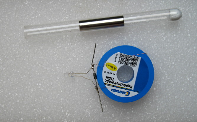
I was lucky to have a small test tube lying around, in which one of my cylindrical magnets just fits. The test tube in turn loosely fits in the hole of the spool. Not really optimal, quite some space is left between tube and spool, but it proved to be useful. For safety it is important to put a piece of paper or wadding in the test tube, such that the magnet cannot hit the bottom of the test tube. The magnet is sufficiently heavy to shatter the glass if it collides with the bottom of the test tube. The picture above shows the test tube with some paper tissue pressed towards the bottom and the magnet halfway the test tube.
The legs of the diode were bent around the plastic rim of the spool and both the diode and LED were firmly attached to the spool with some adhesive tape in order to make the entire construction a little bit more robust.
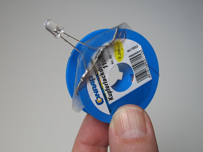
This is the final construction. The test tube is put through the hole and the magnet can be moved around in the test tube by shaking or turning.
![]()
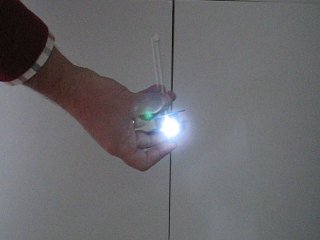
Demonstration of inductive effect with the generator
When a neodymium magnet is used, then the strength of its magnetic field is so high that simply quickly moving it through the hole of the coil already leads to emission of light in the LED. Really stunning results are obtained when the magnet is put in the test tube and when it is shaken. Another stunning effect is obtained when one puts the test tube in the hole of the spool and then quickly withdraws the test tube with the magnet at the bottom.
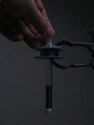
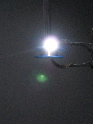
In the left picture above, the test tube with the magnet is through the hole of the spool and in the right picture the test tube is almost withdrawn while it moves upwards at fairly high speed. At that moment there is a bright flash of the LED. Even in daylight the flash can be easily observed, but really spectacular results are obtained in a dimly lit room. A video is available of this experiment. Download size is approximately 5 MByte. Another nice effect is obtained when the flash is directed backwards towards a white wall. This is shown in another video. Download size of that video is approximately 3.5 MByte. The test tube with the magnet is just withdrawn by hand, no special equipment is needed for this.
Even simply turning around the construction of spool, tube and magnet already leads to flashing of the LED. The two pictures below show how the spool is kept near the open end of the test tube and then suddenly the entire thing is turned upside down. The magnet falls downwards through the tube and moves through the spool. A bright flash occurs.
The turning around of the test tube also is demonstrated in a video. Download size is approximately 1.2 MByte.
Most spectacular results are obtained when the tube is shaken fiercely while the spool is kept somewhere near the middle of the tube. A flash occurs two times per cycle, once for motion in each direction. The shaking is demonstrated in a video as well. Download size is approximately 3.5 MByte.
![]()
Discussion of results -- approximate explanation
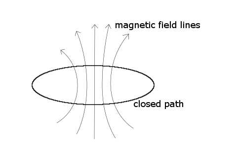
Electricity and magnetism are closely related. When a current flows through a wire, then a magnetic field is produced in circles around the wire.
On the other hand, when a wire is taken in the form of a circle, then a current flows through the wire, when a changing magnetic field is going through the circle. Only changes of the magnetic field lead to currents in the wire.
Magnetic flux
More precisely stated, a changing magnetic flux leads to currents in the circular wire. The magnetic flux is the summation of the magnetic field lines over the area of the disk, enclosed by the circular wire. Suppose there is a magnetic field strength B going through the disk, enclosed by the circular wire and this field strength is the same for every point in the disk, and the field lines are all perpendicular to the disk, then the magnetic flux can be written as π r2 B, where r is the radius of the circular wire and π r2 is the surface area of the disk. Magnetic field strength is expressed in volt-seconds per square meter, also known as Tesla and magnetic flux is expressed in volt-seconds, also known as Weber.
If a coil is made of N turns and the winding of the coil is not too wide nor too thick, then the total magnetic flux through the coil can be approximated by using the above formula for the flux of a single circular wire: π N r2 B. Here r is the average radius of all turns in the coil.
If the magnetic field is not the same for every point in the disk, then the total flux still can be computed, but it becomes much more complicated (see below).
Estimation of magnetic flux through coil
The field strength of a neodymium magnet strongly depends on its size, its shape and on the precise nature of the material it is made of. Usually the magnetic strength of the material is written as N35, N40, N42, N48, N50 etc. The higher the number, the higher the magnetic strength of the material. With an N50 magnet you roughly need 75% of the thickness of an N40 magnet to create the same field strength at the surface of the magnet. The magnet, used in my experiment has a strength of approximately 0.75 Tesla at the surface. Assuming that the field strength is roughly the same everywhere at the two ends of the magnet and that there is no field strength outside the magnet, one can give an approximation of the flux through the coil, when the magnet is just in the coil. The total flux through a single turn then is π*0.0052*0.75 Weber, which is approximately 5.9*10-5 Weber. For a coil, consisting of 1500 turns, the total flux is 0.088 Weber. Note that in this computation the radius of the magnet is used and not the average radius of the turns in the coil. This is a valid approach, because of the assumption that the field strength outside the cylinder of the magnet equals 0.
Estimation of rate of change of magnetic flux through coil
Determining the rate of change of the flux is quite uncertain without good measurements. A very rough estimate is given here, which only gives an idea of the magnitude of the rate of change of the magnetic flux. Rate of change of magnetic flux is expressed in Weber per second, which is the same as volts. So, the rate of change of the magnetic flux is noting else than a voltage!
The magnetic field of the magnet quickly becomes weaker when one is moving away from the magnet, so the flux also becomes weaker. Suppose the flux goes from full strength to half strength over a distance of 1 cm (which is fairly realistic for a neodymium magnet of the used size) and the magnet is moving through the coil at a speed of 1 meter per second (which is a conservative speed estimate when shaking or quickly withdrawing the magnet). In 0.01 second then the flux changes from 0.088 Weber to 0.044 Weber and hence the rate of change of flux is (0.088 - 0.044)/0.01 = 4.4 Volts. Keep in mind that this is a very rough estimate and the number can equally well be 5 volts or 3 volts. But it gives an idea of the order of magnitude.
Estimation of voltage over the LED
Now suppose that a cut is made in the circular wire or the coil and something with high resistance is put between the two ends of the cut, then the voltage across the two ends of the cut equals the rate of change of the magnetic flux. In the example above then there would be a pulse of 4.4 Volts for 0.01 seconds with a lead-in of increasing voltage and a fade-out of decreasing voltage, total pulse time probably can be as high as 0.02 seconds.
In reality, the voltage over the LED will be lower, due to internal resistance of the wire and the pulse also is smeared out somewhat in time due to non-zero size of the winding of the coil, but the numbers above give a good first impression of what kind of voltages can be achieved and how long the flash lasts.
![]()
Discussion of results -- more advanced explanation
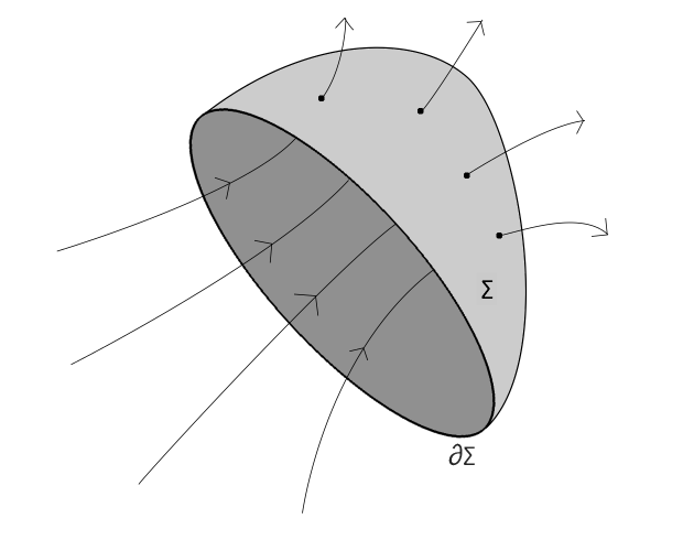
When a closed path is taken and a magnetic field is going through the path, then one can define the magnetic flux Φ as the "summation" of all field lines which go through the area, encircled by the closed path.
A mathematical description cannot be given in terms of simple summations, but it can be given in terms of surface integrals. Suppose the closed path is called ∂Σ and this path forms the border of a surface Σ. Field lines penetrate through the surface Σ and the magnetic flux now can be described as the "number of" magnetic field lines penetrating through the surface Σ.
The flux through the surface Σ can be written as follows:
![]()
Here the vector B is the strength of the magnetic field, expressed in Tesla and this depends on the position in space and possibly on time as well. The vector dA is a vector with the magnitude equal to an infinitesimally small area at the surface Σ and the direction normal to the surface Σ. The quantity B∙dA is the dot-product of B and dA, with the value of B taken at the position of dA on the surface Σ. The remarkable thing is that the flux ΦB does not depend on the actual choice of the surface Σ. For every surface Σ which has the border ∂Σ the flux is the same. So, the flux only is determined by the field B and the closed loop ∂Σ. In many calculations of the flux through a circular border ∂Σ one simply chooses the flat disk enclosed by ∂Σ as a suitable Σ for performing calculations of flux.
The electromotive force (frequently abbreviated as EMF) along the closed loop ∂Σ can be written as
![]()
When a cut is made in the closed loop ∂Σ then the voltage across the two sides of the cut is equal to ε. As the formula shows, the electromotive force does not depend on the magnetic flux itself, but on the rate of change. In classical generators, a high speed mechanical construction is used in order to obtain sufficiently high electromotive force. With modern neodymium magnets the magnetic flux is so strong that one can obtain a good rate of change of magnetic flux even by simple hand-driven motion.
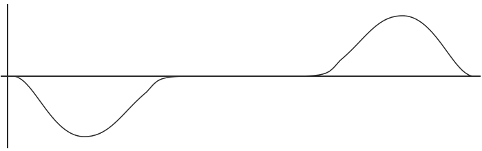
If a magnet is moved through the closed loop ∂Σ then a time-varying flux exists. The picture below shows a magnet which is moving upwards, and a closed path ∂Σ denoted by a red circle. The left picture shows the magnet just entering the closed path ∂Σ. The middle picture shows the magnet halfway, with the closed path around the magnet and the right picture shows the magnet moving away from the closed path again. The big arrows denote the direction of motion of the magnet. A graph of the electromotive force is drawn below the drawing of the magnet. As long as the flux increases (left side of drawing), there is negative electromotive force and as long as the flux decreases (right side of drawing), there is a positive electromotive force along the closed path.
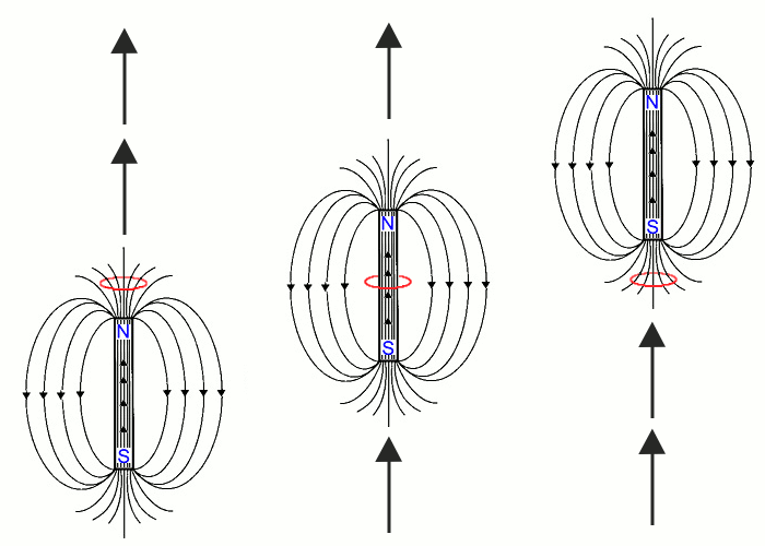
| increasing flux, | constant flux, | decreasing flux, | |
| negative EMF | zero EMF | positive EMF |
Instead of moving the magnet through a closed path, one can also move the closed path itself. It does not matter for production of electromotive force what is the source of change of magnetic flux. This source can be motion of the magnetic field, motion of the closed path, or a combination of this.
Electromotive force of a coil, consisting of many turns
If a coil is made of many turns, which are close to each other, then the voltage, available at the terminals of the coil can be approximated by
![]()
where N is the number of turns around the core and ΦB is the flux through a single turn of the coil.
When a LED is connected to the terminals of the coil, then it only emits light when the forward voltage drop of the LED is exceeded. For most modern high efficiency LEDs the forward voltage drop is somewhere between 2.5 and 4.0 volts. Having a coil of 1500 turns means that the electromotive force around one turn is at least in the order of magnitude of 2 ... 3 mV if the magnet is moved sufficiently fast.
The graph above also shows that the LED can flash two times for each cycle when the magnet is shaken through the coil. Both times there is a positive electromotive force and a negative electromotive force. The electromotive force in one direction causes the LED to emit light, the electromotive force in the other direction causes current to flow through the protective diode, assuring that the LED is not destroyed (see below).
Protection of LED with a diode, connected antiparallel to LED
The diode, connected anti-parallel to the LED is needed to protect the LED from high reverse voltage. A LED only may have current flowing in forward direction. If a reverse voltage is applied then no current flows at all, until the breakdown reverse voltage is reached. At the breakdown reverse voltage the LED suddenly starts conducting. This situation may damage the LED or even completely destroy it.