


Miniature chlorate cell
This webpage describes the construction of a very small chlorate cell, which can be used inside without any problem and which can be operated somewhere in the corner of a small room. The cell can be used to create research quantities of chlorates, yields of approximately 30 grams per day can be achieved routinely. This is not enough for the devoted pyro-enthusiast, but it definitely is worth the effort when one wants to do some interesting chemistry experiments or wants to do some small scale syntheses which require the use of potassium chlorate.
The cost of the cell is around $30 for all the materials, excluding the power supply and the chemicals. The cell can be used many times and in theory it can be used to make several kilos of chlorates, when one has the patience to do so.
![]()
![]() Required
chemicals:
Required
chemicals:
- potassium chloride
- potassium dichromate
- hydrochloric acid (optional, one can do without sacrificing some current efficiency)
![]() Required
equipment:
Required
equipment:
- MMO/DSA anode and a titanium strip which serves as cathode. Sometimes these can be purchased as a set, ready for use in a chlorate cell (e.g. on eBay). The image shows the titanium cathode at the left and the MMO anode at the right.
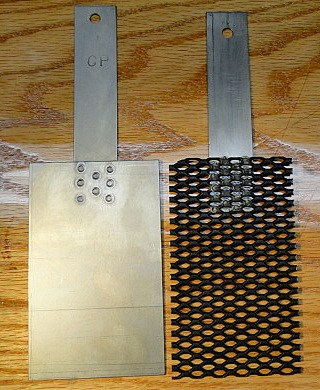
If the ready to use anodes cannot be purchased, then there still is the option of purchasing MMO on titanium substrate mesh and make an anode yourself (e.g. search on eBay with keywords MMO mesh). This, however, requires cutting the mesh in the right size (which is not difficult when a good metal saw is used) and welding a titanium strip to the mesh. The latter requires very hot spot welding and may be hard to achieve for many people.
- Power supply, capable of delivering 5 A at a fixed voltage of 5 volts. An old PC power supply can be converted for this purpose. Very often these can be salvaged from an old PC or obtained for free from a friend or from a scrap yard. For the purpose of powering a chlorate cell one must also keep the 5V of the power supply.
- Good glass bottle with a sturdy, corrosion resistant plastic cap.
- PVC flexible tube with a diameter of appr. 6 mm.
- A miniature drill with a diameter of just 1 mm.
- Sharp knife for cutting hard plastic.
- Filter paper and strongly absorbing paper tissue.
- Heat-resistant glass beaker of 150 ... 250 ml.
- Hot plate, used for heating the beaker of 150 ... 250 ml.
![]() Safety:
Safety:
- Potassium dichromate is toxic and a carcinogen. However, for operating the cell, only a very small quantity is needed. It can be left out, but that will reduce the cell efficiency quite a lot.
- Hydrochloric acid is corrosive.
![]() Disposal:
Disposal:
- There will be no real waste besides some rinse water which is absorbed by filter paper and paper tissue. Remains of a single run can be reused as starting material for a next run. In this way, all of the used potassium chloride is converted to chlorate and most of the potassium dichromate from a single run is recycled as well.
![]()
Preparation of the lid of the cell
When one is doing a small electrolysis experiment, then one usually does this in an open beaker, with a set of electrodes immersed in the solution. This is fine for an experiment which takes a few minutes and runs at a few hundreds of mA, but when one is electrolyzing a solution for hours or even days, at currents of multiple amperes, then a lot of gas is produced. The gas is produced in the form of many tiny bubbles and these produce a dense aerosol above the liquid. This forms a mist, which spreads around the beaker and in time, everything will be covered by a very thin layer of corrosive stuff. During the process, not only salt (or potassium chloride) will be in the mist, but also chlorate, hypochlorite and possibly free chlorine. This mist is amazingly corrosive to metal objects nearby. Metal tools, the nearby power supply, metal parts of furniture, everything will rust like hell when exposed to this kind of mist. So, there MUST be a lid on the cell.
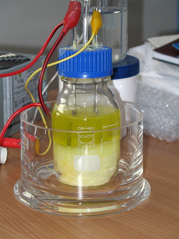
The cell, used in this experiment, is a very simple one, but it has proven to be very effective. A sturdy Schott Duran bottle is taken with an equally sturdy screw cap. The cap is made of a blue plastic, which can withstand temperatures of up to 140 °C and which withstands strong bleach solutions for long times.
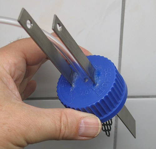
Both the anode and the cathode are welded on a titanium strip with a width of approximately 1 cm and a thickness of 1 mm. With a tiny drill, holes were made in the cap in a pattern, such that 2 lines are made. With a sharp knife the holes were connected, such that the strips can be pushed through the cap. This requires quite some force and one must be careful not to hurt oneself with the knife. The holes in the shape of the lines must be made of such a width that the titanium strips can be pushed through it, but there must be some resistance left, otherwise they will slide through the screw cap.
In the middle of the cap, a 6 mm wide hole must be drilled. A small PVC tube of 6 mm width can be pushed through this hole. Again some force is needed to push the tube through the hole.
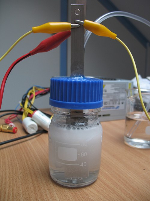
The result is as follows:
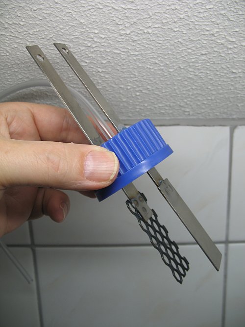
When the electrodes are pushed through the cap, then assure that when the cap is screwed on the bottle, that the electrodes do not touch the bottom, they should be just above it. Still, this kind of connection is not good enough. The mist, produced during electrolysis will be so dense and there will be such a strong flow of gas, that it simply will be pushed along the tiny leaks around the electrodes. So, the space between the electrodes and the cap must be closed with some glue or resin.
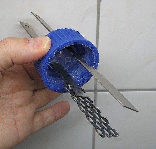
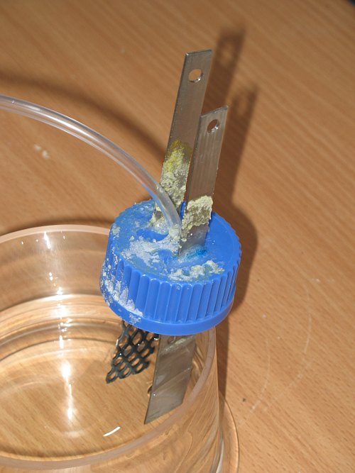
The following two pictures show the construction from below and from above. The view from above shows the glue around the titanium strips. This closes the leaks around the strips, but even this construction could not prevent some leaking. There was no spray around the cell, but there was some leaking of liquid around the titanium strips. This is because the glue does not really stick to the titanium strips, it can easily be peeled off.
The little PVC tube is there to allow the gases to flow away from the cell. The length of the tube is approximately 50 cm. This PVC tube has proven to be quite resistant to the hot fumes leaving the cell. Even after operating 50 hours with a hot cell, the tube looks as transparent as when it was purchased.
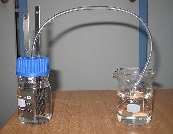
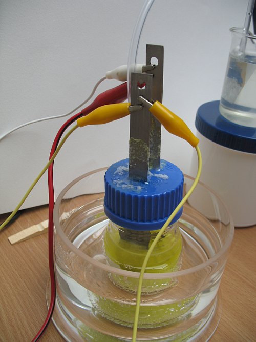
The cell, when closed, looks as follows:
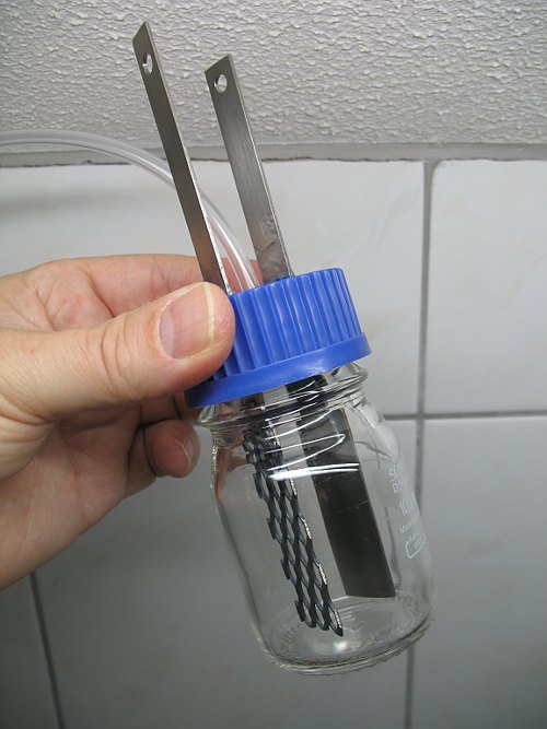
The distance between the electrodes inside the bottle is approximately 2.5 cm (1 inch). From experimenting it was found that this is a nice distance when the cell needs to be operated from a simple 5 volt power supply without current control. The concentrated solution of potassium chloride provides a certain resistance, such that at 5 volt between the electrodes there is a current of approximately 3.5 A. This causes quite some heating of the cell, but that is good. A warm (but not superhot) cell promotes formation of chlorate from hypochlorite. An MMO anode can easily withstand a hot solution.
The distance between the electrodes, however, is not critical. If your construction is somewhat different and there is 3 cm or just 2 cm between the electrodes, then that will be OK as well. It just operates at a somewhat lower or a somewhat larger current. Just aim at a distance of 2.5 cm between the electrodes and then you certainly will end up with something useful.
![]()
Inside use of the cell, use of vent tube and scrubbing chlorine
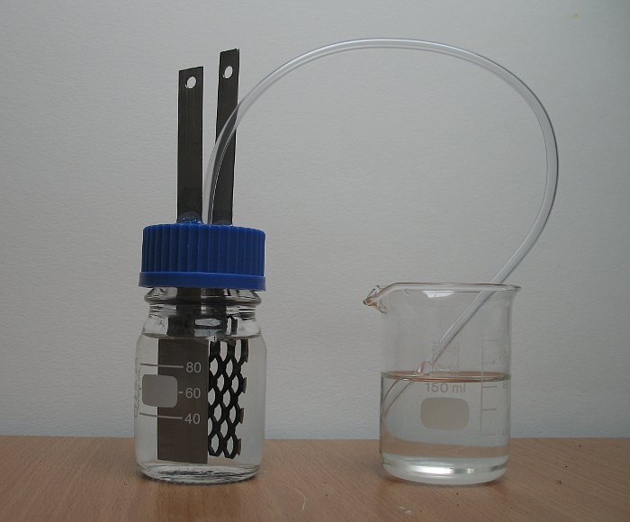
When the cell is used inside, then one must lead the gases from the cell either outside, or through a beaker of water in which some sodium hydroxide is dissolved (the solution only needs to be dilute, e.g. one teaspoon dissolved in 100 ml of water). The sodium hydroxide holds back any chlorine, any mist also is held back by the liquid in the beaker and a colorless and odorless gas mix bubbles to the surface. This gas mix is mainly hydrogen and in the later phases of the electrolysis process it also contains quite some oxygen (volume ratio hydrogen : oxygen ≈ 6 : 1). The construction is simple and effective and allows operation of the cell inside, even in a normal living room. One just has to assure that the end of the vent tube is several cm under the surface of the solution of sodium hydroxide.
It might be tempting to collect the hydrogen from the cell in a separate large glass unit or do funny experiments with it, such as connecting a glass tube to the vent tube and lighting the hydrogen gas, but this should NEVER be done. There can be so much oxygen mixed with the hydrogen, that flash-back into the cell occurs and all if it explodes. There is enough explosion force to shatter the complete cell, especially if a normal glass jar is used with 50 ml or so of hydrogen/oxygen mix in it!
![]()
Operation of the cell
The cell must be operated with a concentrated solution of potassium chloride. Preparation of such a concentrated solution can be done as follows:
- Take 35 to 40 grams of potassium chloride and put this in a beaker.
- Add water, such that the volume becomes 130 ml. This is not the same as adding 130 ml water! You have to top up to 130 ml.
- Dissolve the potassium chloride. This may be difficult when it is cold. Just for convenience put the beaker in a pan with some warm tap water. This makes dissolving of the potassium chloride more easy.
- If fertilizer grade potassium chloride is used (so called N-P-K rating equal to 0-0-60), then it might be necessary to filter the solution. The solution, transferred to the cell must be absolutely clear, otherwise you will have difficulty to separate solid crap from the potassium chlorate formed in the cell.
- Transfer 100 ml of solution to the cell.
- Keep the remaining 30 ml, it is needed to top up the liquid during electrolysis. To this 30 ml of liquid add 0.5 ml of 10% hydrochloric acid and mix this. Set this mix aside for later use.
- Put the end of the vent tube several cm under the surface of a dilute solution of sodium hydroxide in a separate beaker.
- Connect anode and cathode and apply 5 V. If a higher voltage is used, then use appropriate series resistors or power diodes to limit the current through the cell (how this must be done for a 12V power supply is described here). Never apply too high a voltage to the cell without limiting resistors. This will damage the anode! Also assure that the polarity of the applied voltage is correct. Failure to do so WILL destroy the electrodes!
When all is setup correctly, then the cell will start bubbling and it slowly digests the chloride to make chlorate from it. Bubbles of gas will leave the vent tube in the beaker with dilute solution of sodium hydroxide. Initially there may be a faint smell of chlorine, but soon the bubbles of gas in the beaker will be totally odorless. The cell can be operated inside, just assure that there is some ventilation.
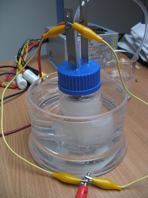
There will be vigorous bubbling and soon the cell will heat up. It is good if it becomes warm, but it should not become so hot that one cannot bear touching it. During operation, the cell became too hot and it was decided to cool the cell by putting it in a water bath.
When the cell is operated in this way, it can be left unattended for many hours. The only thing one needs to do every 10 hours or so is topping up the liquid in the cell with some fresh solution of potassium chloride. The volume of liquid slowly decreases due to formation of hydrogen and oxygen and due to losses through evaporation. Quite some water vapor leaves the cell through the vent tube!
![]()
Increasing cell efficiency by reducing back-reduction at the cathode
The vent tube in the cell has a nice side effect. It allows one to see how fast the cell is operating, by counting bubbles leaving the vent tube. This can go too fast, but when a digital camera is used and a little movie is made, then one can easily count the number of bubbles per 15 seconds or so.
While the cell was operated, there was a slow decrease of the number of bubbles, delivered through the vent tube. After two hours of operation, the number of bubbles per second was only a fraction of the number of bubbles, produced just after powering up. It slowed down more and more! The cell also was running excessively hot, even when it was cooled in a water bath. The current still was around 3.5 A, but much less hydrogen was produced. So, the question is, where is all the energy going?
Ideally, at the cathode there is the following reaction: 2H2O + 2e → H2 + 2OH–
Hydrogen escapes from the cell and hydroxide ion remains behind in solution.
At the anode, chlorine is produced. Initially, the chlorine bubbles away from the solution. The effect of this is that the solution becomes alkaline, due to the unbalanced hydroxide, produced at the cathode at the same time. A few minutes after power on, chlorine hardly bubbles out of solution anymore, but it reacts with the hydroxide, giving chloride and hypochlorite:
Cl2 + 2OH– → Cl– + ClO– + H2O
An internet survey revealed that at low current densities (less than 200 mA per cm2, which certainly is the case in this miniature cell) on a titanium cathode there will be an important side reaction, in which hypochlorite ion is reduced back to chloride:
ClO– + 2e + H2O → Cl– + 2OH–
So, the hypochlorite which is produced with great effort (from chlorine at the anode and hydroxide, formed from water at the cathode) is converted back to chloride. This reaction is exothermic, the energy needed to make hypochlorite from chloride is now converted to heat.
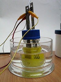
Adding a small amount of chromate or dichromate to the cell significantly reduces the effect of back-reduction. So, the cell was opened and a few ml of water were added in which approximately 200 mg of potassium dichromate was dissolved. After mixing and powering on again this looks as follows:
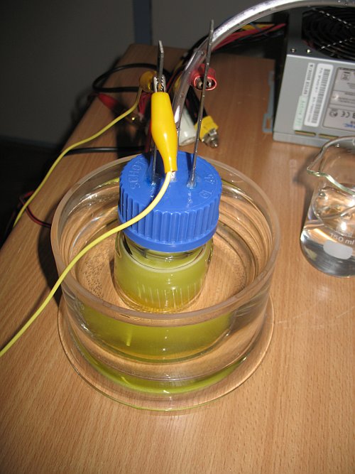
The dichromate leads to formation of a very thin (nanometer size) layer of chromium hydroxide around the titanium cathode. This tiny layer is a very effective shield, which prevents hypochlorite ions to touch the cathode, while it still allows positive ions and water to touch the cathode. It does add some ohmic resistance, but the back-reduction of hypochlorite is very effectively suppressed.
After this modification, two remarkable effects were noticed:
- Hydrogen production more than doubled while the current remained nearly the same, so in practice the increase of ohmic resistance only is small.
- After half an hour or so, the cell and also the cooling water around the cell were much cooler. This can be explained, because now there is not an exothermic reduction of hypochlorite anymore.
Two little movies were made, one movie just before adding the dichromate, and the other movie after adding the dichromate. The difference is striking:
- video of hydrogen bubbling before adding dichromate
- video of hydrogen bubbling after adding dichromate
Download size of these videos is approximately 2.5 MByte each.
So, after adding the dichromate, all electric current again is put in making hydrogen at the cathode and oxidizing things at the anode and no or only little back-reduction occurs after this modification.
![]()
Increasing cell efficiency by controlling the pH
Another (less severe) problem with the cell is the buildup of hypochlorite in solution, which is not converted to chlorate in solution, but is oxidized further at the anode. The mechanism is explained in this section. The first step towards chlorate is the formation of chlorine, followed by formation of hypochlorite:
- Chloride ion is converted to chlorine at the anode: 2Cl– – 2e → 2Cl• → Cl2
- At a pH close to 6, the chlorine disproportionates as follows: Cl2 + OH– → HOCl + Cl–
- At a pH close to 10, the chlorine disproportionates as follows: Cl2 + 2OH– → ClO– + Cl– + H2O
As the reaction equations demonstrate, independent of pH, two electrons are needed for formation of a single hypochlorite ion. At the cathode, at the same time one molecule of H2 is formed.
When no special precautions are taken, then the pH in the cell slowly approaches a certain fairly alkaline value somewhere around 10 until some equilibrium value is reached.
It turns out that there are two main mechanisms for formation of chlorate in the cell. The main (and most desirable) mode of chlorate production is disproportionation of hypochlorite to chlorate, which frequently is written as:
3ClO– → 2Cl– + ClO3–
This reaction is very slow, even at elevated temperatures and in practice it does not contribute to chlorate formation in a cell. However, when pH is around 6, then a large part of the hypochlorite is present as hypochlorous acid and then the reaction proceeds much faster, especially at a somewhat elevated temperature (e.g. 60 °C):
2HOCl + ClO– → 2Cl– + ClO3– + 2H+
In a cell, which is allowed to run for a long time without pH-control, the pH becomes much higher than 6. Chlorate production hardly occurs in solution at such a high pH and hence the concentration of hypochlorite increases. The concentration becomes so high that besides discharge of chloride ions at the anode the discharge of ClO– ions also becomes an important reaction. The discharge of ClO– ions immediately is followed by reaction with water and rearrangement of atoms. This process is remarkably complex and still not fully understood, but the total net reaction equation can be written as follows:
6ClO– + 3H2O – 6e → 6ClO• + 3H2O → 2ClO3– + 4Cl– + 6H+ + 1˝O2
Already 12 electrons were needed to make 6ClO– (2 electrons per hypochlorite ion) and now another 6 electrons are needed to make 2ClO3–. So, in total 18 electrons are needed for making 2ClO3–. This makes up a total of 9 electrons per chlorate ion. This is a loss of efficiency, because when the chlorate is produced in the solution by disproportionation of hypochlorite, then only 6 electrons are needed per chlorate ion. By careful pH control one can increase cell efficiency. In this small and simple cell it is decided not to do so. Careful pH control is fairly complicated and laborious. So, in this cell the 33% lower efficiency of 9 electrons per chlorate ion is accepted. For an industrial setup, cell efficiency is very important, but for a hobby setup, a somewhat lower efficiency still is acceptable, one just needs to wait a little longer before a crop of potassium chlorate can be taken out of the cell. So, no real pH-control was done, but when the cell had to be opened anyway for topping up the liquid, then some acid was added as well. This strategy is a decent compromise between complexity of operating the cell and efficiency.
![]()
Behavior of cell during its operation
While the cell is running it remains warm, but not really hot (assuming that some potassium dichromate is added). Hydrogen gas is produced at the cathode at a high speed, and there also is some oxygen at the anode. Already after a few hours of continuous operation you can see formation of a crystal layer at the bottom of the cell.
After 10 hours of operation, the water level in the cell has dropped considerably. This is the moment to top it up with some fresh solution of potassium chloride. For this purpose, 15 ml of the slightly acidic solution of potassium chloride is taken, which was prepared before powering up the cell. A layer of almost 1 cm of crystals of potassium chlorate will be present in the cell at this time.
Next, the cell was allowed to run for another 8 hours without any interaction. After this period, again 10 ml of slightly acidified solution of potassium chloride was added in order to top up the liquid level in the cell. After 18 hours a thick layer of crystals of potassium chlorate is present.
The electrodes partially are covered by the crystals of potassium chlorate, but the crystals do not stick to the electrodes. The partial coverage of the electrodes leads to an increase of the ohmic resistance of the cell and the current drops somewhat. After 18 hours, the current has dropped well below 3 A. The cell still is quite hot, but not as hot as it is 10 hours earlier.
The last 5 ml of solution of potassium chloride was added approximately 22 hours after switch on. After that, the cell was allowed to run for another 4 hours, making the total run time 26 hours. At this point the current had dropped to just 2.5 A and the cell became quite cool. It was decided to stop it, because the layer of crystals has become so thick, that more than half of the electrodes is covered.
Leaking of liquid from the cell, despite the glue around the electrodes
There only was one real problem while running the cell and that is creeping of liquid from the cell along the electrodes. The liquid creeps under the layer of glue. The glue does not stick to the titanium strips. There is no spraying above the bottle, but the cap becomes covered by a crust of salt and also the titanium strips become covered by a crust of salt. No smell can be observed around the cell, but the salt solution gives a chlorine-like smell when some of it is scraped from the cap and a drop of hydrochloric acid is added. The following picture shows the crust of salt on the cap and the titanium strips. This is 26 hours after switch on.
This effect is not good, but it is not so severe that it really impairs proper functioning of the cell. It, however, leads to extra losses. Looking at the amount of crust, it is estimated that approximately 1 ml of liquid is lost in this way, which is around 1% of the total amount.
![]()
Work up of the potassium chlorate, recovering waste
After 26 hours, the cell was switched off. It is best to take the electrodes out of the solution, immediately after switching off. The cathode is protected against corrosion as long as voltage is applied, but this protection disappears when the cell is switched off. The electrodes must be rinsed very well with lukewarm tap water, such that all salt-remains are removed.
Cooling down of cell content in order to maximize crystal yield
The cell content itself must be put aside and allowed to cool down. Another plastic cap without holes can be tightly screwed on the bottle and then the entire bottle can conveniently be cleaned under running tap water and put aside to allow it cooling down to room temperature. When it is at room temperature, then it must be put in a freezer, such that it cools down to well below zero, but the liquid in the cell should not freeze.
At the same time also put a beaker with 30 ml of distilled water in the freezer and allow this to partially freeze.
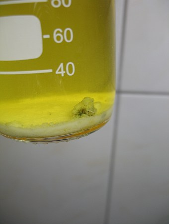
When the cell is ice cold and the 30 ml of water is partially frozen, then take them out of the freezer. The cell at this stage looks as follows:
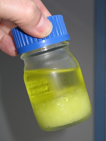
First cleanup step, removal of adhering yellow liquid
Pour as much as possible of the yellow liquid in a clean beaker and set this aside. When the liquid has been decanted, then shaking the solid will release some more liquid and make the layer of potassium chlorate more compact. Repeat this careful shaking and decanting until really no more liquid can be squeezed out. About 50 to 60 ml of liquid can be recovered. If a few crystals go into the beaker with the yellow liquid this is not bad, these crystals are not lost, they will be used as a starting point for a next run.
With a plastic spoon now scrape all of the solid from the bottle and put it on a filter paper. A coffee filter will do the job. Put the filter on a small pile of paper tissue (toilet paper works very well) and simply put the crystals of potassium chlorate on the filter. Allow to stand for a few minutes. Almost all adhering liquid is absorbed in the filter and the underlying paper tissue. Do not put the crystal mass directly on paper tissue, always have a piece of filter paper between the crystals and the tissue. Failing to do so will lead to great mechanical losses. Tissue paper becomes very soft when it becomes wet and it will be hard to scrape the crystal mass from the wet tissue.
Next, with a plastic spoon carefully scrape all of the crystal mass from the filter paper and put the crystals in a clean beaker. Now take the 30 ml of ice cold distilled water and pour this on the fairly dry and light yellow crystal mass. Swirl for a few tens of seconds and then decant as much as possible of this liquid into the recovered yellow liquid from the cell. About 15 to 20 ml of liquid can be recovered.
Again, put the crystal mass on a filter paper, which is put on a fresh and dry pile of tissue paper. Allow to stand for a few minutes, such that the crystals become fairly dry. Again scrape the crystals from the filter paper and put them in a clean glass beaker.
At this stage you will have off-white or pale yellow crystals. These crystals have a faint odor of bleach and contain some hypochlorite and remains of the dichromate. For most synthetic purposes, this potassium chlorate already can be used, but it is not recommended to use it for pyrotechnic purposes (actually it is better to use no chlorate at all for pyrotechnic purposes, but that is another issue).
Second cleanup step, recrystallization and making snow-white really pure crystals
To the pale yellow crystal mass in the glass beaker add approximately 70 ml of distilled water. Put the glass beaker on a hot plate and heat until the liquid starts boiling. While doing so, stir the liquid with the crystal mass in it with a plastic or glass rod in order to prevent excessive bumping. Do not use a metal spoon for stirring. When the liquid boils, most or even all of the crystal mass will have dissolved. If after a few minutes of boiling not all of the crystals have dissolved, then add 15 ml of distilled water and again bring the liquid to a boil. If still not all of the crystals dissolve in the liquid, again add 15 ml of distilled water. Keep doing so, until all of the crystals have dissolved. Usually no more than 3 additions are needed, if 4 additions are needed, then your cell was running very well. The boiling assures that all hypochlorite which still was present is destroyed.
If all crystals have dissolved, then switch off the hot plate and slowly let all of it cool down to room temperature. While it cools down, a lot of crystals will form, both at the bottom and at the surface of the liquid. Just let this process of crystal formation do its work. If it is not disturbed too much, large crystals will be produced, which makes handling easier and reduces losses in the final rinse stage.
If the liquid has cooled down to room temperature, then a lot of crystals will be in the liquid, it may even look as if it is completely filled with crystals. Put this liquid with all the crystals in it in the freezer and allow to cool down well below 0 °C, but the liquid should not freeze. Also put 25 ml of distilled water in the freezer and allow this to freeze partially.
Take the ice cold liquid from the freezer, stir with a plastic or glass rod to make the crystal mass more compact and decant as much as possible of the cold liquid (which is very pale yellow) into the yellow liquid, recovered in the first cleanup step. Then scrape all crystals from the beaker and put them on a filter paper, which in turn is placed on a pile of paper tissue. Allow absorption of liquid for a few minutes.
Transfer the fairly dry crystal mass to a beaker and add the 25 ml of ice cold water. Swirl for a few tens of seconds and then decant as much as possible of the rinse water into the beaker and again put the crystals on a piece of filter paper, which is on a pile of fresh and dry paper tissue. Allow absorption of as much as possible of the adhering liquid. The more of this liquid is absorbed, the better the purity of the final product.
At this point, a clean crystal mass is obtained, which looks white like fresh-fallen snow. Scrape the crystals from the filter paper and put them on a clean glass plate or on a watch glass or petri dish.
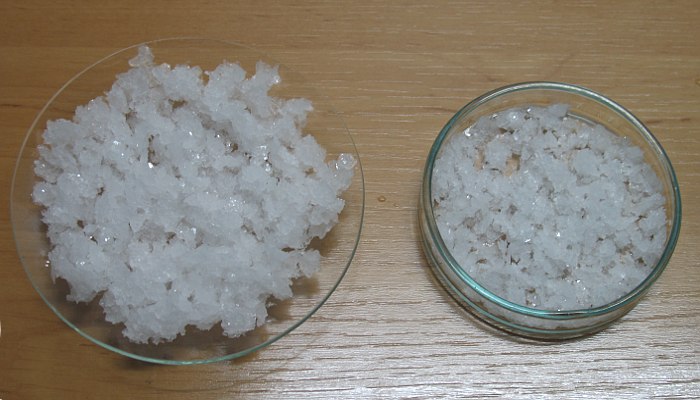
Put the material in a warm dry place free of dust (e.g. on a central heating radiator) and allow to dry for a day. After one day you will have perfectly dry crystals. Occasionally stirring the crystal mass somewhat helps speeding up the drying process. Transfer the still somewhat warm crystals to a clean and dry vial for storage. Well dried potassium chlorate has infinite shelf life if stored in a tightly closed vial.
![]()
Using the waste liquid as starting point for a next run
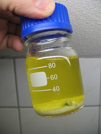
At this point you are left with a nice crop of potassium chlorate and about 150 ml of yellow waste liquid remains. If you intend to use the cell immediately for a next run, then boil down the liquid to approximately 110 ml. If you don't need to run the cell immediately, then just put the liquid in a wide open beaker in a dust-free place and allow the water to evaporate. In one or two days its volume will be less than 110 ml. If too much water has evaporated then that is no problem, it simply can be replaced.
The 110 ml of waste liquid can be put in the cell-bottle until it is used again for a next run. The picture below shows the bottle with the waste liquid. A thin layer of impure potassium chlorate can be seen on the bottom. This makes up for a nice starting point in a next run.
For a next run, take the waste liquid, add 20 to 25 grams of potassium chloride and dissolve this in the yellow liquid. This gives around 125 ml of new concentrated solution, which also already has quite some chlorate dissolved in it. With this 125 ml of liquid the entire process can be started again, 100 ml is used initially and the remaining 25 ml can be used to top up the liquid level during electrolysis.
After two recoveries it will be necessary to replenish the potassium dichromate. Use 100 mg (half of the initially added amount) and add this to the 125 ml of liquid before operating the cell.
![]()
Estimation of the current efficiency of this cell
After drying, the yield of pure potassium chlorate was weighed and it was 30 grams. The cell has been running for 26 hours, with a current between 3.5 A and 2.5 A just before switch off. The average current over this period is not known, but it is expected to be above 3 A (most of the time the cell was running at 3.5 A, only after 15 hours or so the current slowly dropped due to partial coverage of the electrodes by crystals). For this computation, it is assumed that the average current was 3.2 A.
The cell has been running for 26 hours. This means that 83.2 Ampere-hours of charge have been applied. This is 83.2×3600 = 3.0•105 Coulombs of charge. According to Faraday, approximately 96.5•103 Coulombs of charge equals 1 mol of electrons. So, in total 3.11 mol of electrons is produced in this electrolysis run.
Theoretically, at 100% current efficiency 6 mol of electrons are needed for making 1 mol of potassium chlorate. With 3.11 mol of electrons, 0.518 mol of potassium chlorate can be made. In reality, 30 grams of potassium chlorate is isolated, which is 0.245 mol of potassium chlorate.
Based on this info, cell efficiency would be equal to 0.245/0.518, which is just over 47%. In reality, the efficiency of the cell is better, because the starting liquid for the next run already contains quite some potassium chlorate. A few grams can be seen on the bottom of the bottle, and the liquid above it also is expected to hold a few grams of potassium chlorate. Also some of the liquid is lost in the paper tissues and filter paper. If the additional amount of potassium chlorate is 5 grams (which is a pessimistic estimate), then the total amount would be 35 grams, which is 0.286 mol. With this number the current efficiency is 0.286/0.518, which is 55%.
Whatever the precise efficiency, it certainly is better than 50%, which is not bad for such a simple cheap cell with the only optimization being the addition of a little amount of potassium dichromate and a few drops of dilute hydrochloric acid when the liquid level is topped up again.
Probably the biggest loss in the final workup is in the last few hours of the electrolysis. The cell was quite cool, it only felt lukewarm when it was touched. At the end when the cell was stopped, there was a strong bleach smell, indicating that quite a lot of hypochlorite is present in the liquid. This is not converted to chlorate, due to the low temperature of the cell. The liquid simply was decanted from the crystal mass. Probably the yield would have been somewhat higher if the cell was taken out of the cooling bath in the last 6 hours or so. The hypochlorite, however, is not lost, it already gives a nice start in the next run.
![]()
Results of a second run
The cell has been running for another 24 hours, with the worked up remains of the previous cell. It was necessary to top up the liquid two times and the entire procedure, as shown above, is followed for this second run. The second run had a similar yield of pure potassium chlorate, it weighed in at 32 grams. The cell was started with a higher temperature, the solution was brought to 50 °C or so before powering up the cell. This was done by placing the cell in the water bath, as shown in the pictures above, and the bath was filled with hot tap water.
Estimated current efficiency, based on yield, now is somewhat higher, it is nearly 55%. This estimated current efficiency also will be close to the real current efficiency, because now there was a startup with some chlorate and hypochlorite present already. The waste remains for the next run compensate approximately for the waste remains from the previous run, so now the yield of pure potassium chlorate will be close to what the cell really made. The only real losses are the amounts of liquid absorbed by the paper tissue and filter paper and salt solution creeping up along the electrodes. Taking into account that kind of losses the current efficiency might be 2% to 3% higher than the value of nearly 55%.
The waste remains can be used for a third run. The color of the waste liquid shifts a little bit towards green. This might be due to partial reduction of chromium(VI) to chromium(III). It is remarkable how clear the waste liquid is. The anode and cathode keep up very well and no anode particles at all are produced during the electrolysis. MMO/DSA anodes really are beautiful anodes for chlorate production.
![]()
A third run without cooling
The remains of the second run were used as a starting point for a third run. The third run was done in the same way as the second run, with one major difference. The bottle was not put in a water bath for cooling. This results in a few main differences:
- The most obvious difference is that the cell becomes very hot and one cannot bear touching it for more than a second or so.
- Another main difference is that only a thin layer of potassium chlorate is formed at the bottom. After 18 hours there just was a 5 mm layer of potassium chlorate. In the much hotter liquid, the chlorate remains in solution. This is advantageous, the electrodes are not covered by crystals and hence full current can be applied.
- After approximately 20 hours quite suddenly a lot of gas was produced at the anode. In one hour the situation changed from hardly any gas production to a lot of gas production at the anode. The gas is not chlorine (no smell), it hence is oxygen.
Especially the last observation is a very interesting one. It is known that an MMO anode is not capable of making perchlorate. When almost all chloride is used up, then the only other thing which can be further oxidized is water. A small test was done by dissolving a few grams of potassium chloride in a few ml of boiling water and add this to the cell. Almost immediately after adding this new potassium chloride the production of gas at the anode stopped, while gas production at the cathode still was the same. After approximately 1 hour, however there was quite some gas production at the anode and half an hour after that it was very strong again. At that point the cell was switched off, the electrodes removed and rinsed and the liquor in the cell allowed to cool down.
The final yield of this run was 35 grams, which is 0.286 mol. This could be achieved in 21.5 hours of running the cell. The cell current now remained 3.5 A. In 21.5 hours, 2.81 mol of electrons was produced. In an ideal world this would make 0.468 mol of potassium chlorate. The current efficiency now is 0.286/0.468, which is 61%.
Running the cell without cooling can be attractive, but it is much harder to the cell materials. The part of the little PVC vent tube, which is under the cap has become opaque/white, while in the 50 hours of running in the two previous runs it remained clear. The anode and cathode are not affected by the high temperature, at least not visibly.
![]()
Some remarks on the use of glass in a cell
Discussion on sciencemadness.org revealed that some people experienced problems when they were running a large chlorate cell in a glass jar. After some time, the glass was etched and an impervious layer deposited on the electrodes, hindering free flow of current. I did not observe any of these problems in the little cell, but it is worth mentioning this experience of other people. It might be that other people had problems because
- they used much higher currents (in the range of 50A to 100A)
- they did not use Schott Duran glass, but some other glass, possibly less resistant to chemical attack.
The main cause of the problems with glass may be the slow dissolution of glass in the alkaline liquid. Addition of dichromate reduces this problem somewhat, because it provides some buffering of the solution and in general the cell may run at a somewhat lower pH. The addition of 0.5 ml of 10% hydrochloric acid in the liquid for topping up, as I suggested, also may reduce the problems with glass.
![]()
An attempt to make potassium bromate with the same cell
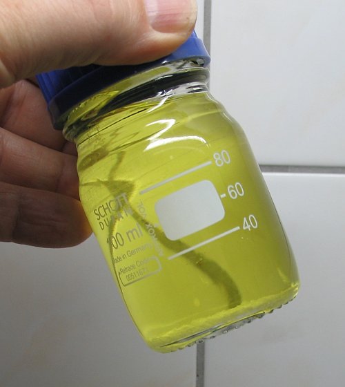
The same setup is used, but instead of a solution of potassium chloride, a solution of potassium bromide is taken. Around 50 grams of potassium bromide were dissolved, such that 130 ml of liquid was obtained. Some heating was needed to get all of the potassium bromide dissolved in acceptable time. Again, 200 mg of potassium dichromate was added as well.
A volume of 100 ml of this liquid was put in the cell and it was powered up, just like the chlorate cell. The cell was put in the water bath, and the bath was filled with lukewarm water. The solution of potassium bromide also was lukewarm.
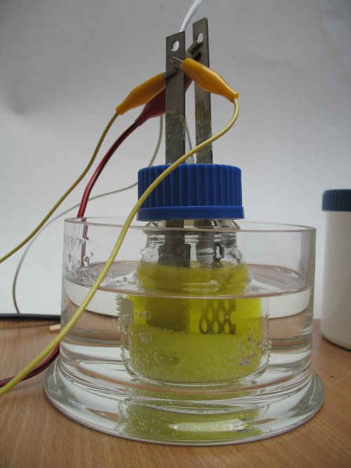
Immediately after power up, a current of 3.5 A was taken from the 5V power supply. Exactly the same as with potassium chloride. When power is applied, one can nicely see the bromine flowing from the anode and collecting of bromine at the bottom of the cell.
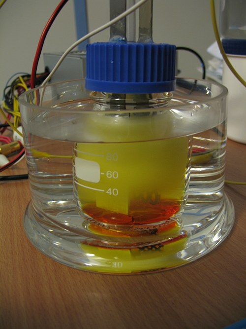
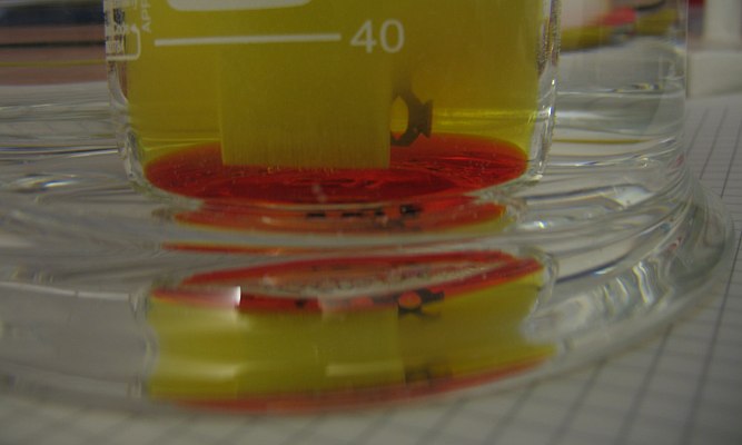
The picture above shows the liquid in the cell with the yellow color, due to added potassium dichromate. At the bottom there is a more dense layer, containing the red elemental bromine. A close-up demonstrates the sharp boundary between the solution of bromine and the liquid above it.
Already 1 hour after switch-on, the first crystals of potassium bromate could be observed. These crystals collected at the bottom, but also crystals were deposited on the anode. After two hours, the entire MMO-mesh was covered with a thin off-white crust of crystals. The current, however, still was well over 3 A.
At this point a layer of a few mm of potassium bromate crystals had collected at the bottom, but also something very undesirable could be seen. At the top of the MMO-anode, a thick dark grey flocculent blob could be observed and when the bottle was carefully tapped the blob fell off the anode. There also were many dark green/grey spots in the layer of crystals of potassium bromate. The cell was switched off immediately and the electrodes were cleaned thoroughly.
The cathode is not damaged, but the anode is damaged severely. The MMO mesh still looks pristine, but the titanium strip to which the MMO mesh is welded is corroded severely. It shows strong pitting and it was covered with a grey layer, which simply could be wiped off with a finger. The picture below shows the flocculent blob of material, which fell off the anode.
So, it appears that anodes on a titanium strip are not suitable for making bromates. The MMO mesh itself can withstand the bromate in the solution, but the strip to which it is welded cannot. In just a few hours of operation it was severely corroded. In a chloride/hypochlorite/chlorate solution, the titanium is passivated by a thin oxide layer, but in an equivalent bromine-environment the passivation apparently is not so strong that it can prevent corrosion of the underlying metal.
The conclusion is that an MMO anode on a titanium substrate should not be used for bromate production. Bromate production, however, can be done fairly easily on a small scale with graphite anodes or with platinum. Actually, bromate production even is easier than chlorate production, because the bromine does not tend to bubble out of solution.
![]()
Synthesis of cesium chlorate from cesium chloride
In another experiment, some cesium chlorate is made. Sometimes, one can obtain cesium chloride for very good prices (i.e. around $10 per 100 gram) and I fortunately came across such a situation. I have taken the opportunity and used this to make very pure CsClO3.
For this purpose, a 250 ml bottle was used instead of a 100 ml bottle and the same electrodes were used. They were pushed somewhat deeper into the lid of the bottle, but essentially the cell was of the same type.
The process of making cesium chlorate by means of electrolysis of cesium chloride is very similar to the process of making potassium chloride. The main differences are
- When cesium chlorate is electrolysed, no saturated solution should be used
- Dichromate must be added in much smaller quantity and this must really be pre-dissolved before adding it to the liquid. Cesium dichromate has a remarkably low solubility in a concentrated solution of cesium chloride.
Taking these two differences into account, the following procedure can be used for making cesium chlorate.
- Dissolve 100 grams of cesium chloride in 150 ml of water and top up to 250 ml. If the solution does not become totally clear, then filter it.
- Dissolve around 50 mg of potassium dichromate or chromium trioxide in 2 ml of water and add this solution to the solution of cesium chloride. It might be that a sticky and somewhat slimy precipitate of cesium dichromate is formed. If this is the case, then heat the solution and stir until all of the solid has dissolved. The resulting solution will be bright yellow.
- Electrolyse the solution using a 5 V power supply and adjust the distance between anode and cathode such that approximately 3 A of current is flowing through the cell. Keep the current flowing for approximately 24 hours. The liquid will become quite hot. This is good, we want the cell to be hot. Only a small amount of solid cesium chlorate will settle at the bottom (if any at all).
- Dissolve another 40 grams of cesium chloride in an as small as possible amount of hot water. If boiling hot water is used, then only around 50 ml of very concentrated solution is obtained.
- Add this very hot and concentrated solution to the liquid in the cell and let it electrolyse for another 24 hours. At a certain point in time, the current will drop quite a lot in just an hour time and at that point in time the cell will cool down also. When this happens a lot of solid cesium chlorate will settle at the bottom, as shown by the picture below.
- Switch of the power supply and disassemble the cell. Let the liquid cool down to room temperature. When it has cooled down, then let it cool down further in a freezer, such that its temperature goes well below 0 °C, but the liquid should not freeze.
- Decant the ice cold yellow liquid as much as possible. Shaking and/or stirring with a plastic or glass rod may help making the precipitate more compact and being able to decant more of the yellow liquid. Keep this liquid, it still contains some cesium which may be recovered.
- Build a heap of 4 sheets of paper tissue or 10 sheets of toilet paper and put a coffee filter on top of that. Put the wet crystal mass on the coffee filter and allow the liquid to soak into the paper tissue. Repeat this step one or even two times, until only a small amount of moisture is absorbed by the paper tissue. Do not put the crystal mass directly on the paper tissue, it is important to have a coffee filter in between. Scraping the crystal mass from a completely wet and pulp-like tissue is very hard.
- Transfer the now fairly dry crystal mass to a clean beaker and add 200 ml of water. Put the beaker on a hot plate and bring the liquid to a boil. If not all of the cesium chlorate dissolves, then add 20 ml of water while stirring, bring the liquid to a boil again and repeat this until all of the cesium chlorate has dissolved.
- Let the liquid cool down, first to room temperature and then put it in a freezer and allow it to cool further well below 0 °C.
- A lot of crystals will be formed during cooling down. Decant the very pale yellow liquid (keep it, add this to the bright yellow liquid you already have), dry the crystal mass with a fresh coffee filter and paper tissue.
- Transfer the crystal mass to a beaker and add 100 ml of ice cold water. Swirl for a while and then decant the liquid (which is nearly colorless).
- For a third time put the crystal mass on a coffee filter and a heap of paper tissue and dry as much as possible. At this stage you will have snow white crystals.
- Finally transfer the crystal mass to a clean glass plate and allow the crystals to dry on a warm place free of dust and moisture.
At the end of this process you will have 140 to 150 grams of pure dry cesium chlorate. This is a cesium recovery of approximately 80%.
When the crystal mass is scraped from a coffee filter, then one should not be too greedy. Try not to scrape off the last small crystals. Accept some losses, because when one is scraping strongly on the coffee filters, then also many fibers are taken with the crystals and these add hard to remove contamination.
Treatment of waste
After the workup of the cesium chlorate, there will be the following waste items:
- 3 coffee filters with cesium chlorate crystals sticking to them
- a lot of wet paper tissue
- approximately half a liter of waste liquid, containing still some cesium
The picture below shows one of the coffee filters, almost dry after it was stored for several hours:
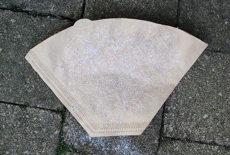
The paper tissue should be put in a tub of water and the totally wet tissue can be wrapped in a plastic bag and then thrown in the household waste bin. The waste is not particularly toxic and the totally wet tissue wrapped in the plastic does not introduce any risk of fire.
The coffee filters can be treated in the same way, but a more funny way is to light them and see how fast the paper with the chlorate burns. A video is made of lighting one of these filters. The still slightly damp filter hardly burns at the places where there are no cesium chlorate crystals but the center part burns fiercely, even while it still is moist. A video nicely demonstrates this (download size is 8.7 MByte).
The waste liquid can be boiled down to 100 ml or so and another 15 grams of cesium chlorate can be recovered from this. Do not mix this 15 grams of cesium chlorate with the main crop, it most likely is less pure, unless two recrystallize steps are taken on it. Another option is to treat the half a liter of liquid with a solution of approximately 20 grams of sodium perchlorate and then boil down to 100 ml. In that case, approximately 20 grams of cesium perchlorate can be recovered. When this step is carried out, then around 90% of all cesium is recovered.